Emission Tail of Indium Phosphide Quantum Dots Investigated using the FS5 Spectrofluorometer
Introduction
Semiconductor quantum dots (QDs) have unique tuneable photoluminescence properties which lend them to a range of important technological applications including solid-state lighting, displays, photovoltaics, and biomedical imaging. Indium phosphide quantum dots have attracted significant interest as an environmentally friendly and non-toxic alternative to traditional heavy metal based QDs containing cadmium and lead.
Quantum dots composed solely of indium phosphide (Inp) are non-emissive due to non-radiative recombination occurring at trap states on the surface of the InP. To obtain emissive quantum dots the indium phosphide core is coated with a layer of a higher bandgap semiconductor such as zinc sulphide (ZnS) to form a core-shell heterostructure which passivates the trap states and greatly increases the photoluminescence quantum yield (Figure 1). In order to further improve the brightness, stability and colour range of InP/ZnS QDs, relationships between the composition and photoluminescence properties need to be established. In this application note, the FS5 Spectrofluorometer is used to carry out a steady state and time-resolved characterisation of novel InP/ZnS QDs.
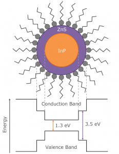
Figure 1: Typical structure and band energy diagram of core-shell InP/ZnS quantum dots.
Materials & Methods
A solution of InP/ZnS QDs in toluene was prepared with an absorbance of 0.15 at 500 nm. The absorption and photoluminescence properties were characterised using an FS5 Spectrofluorometer equipped with an SC-05 Cuvette Holder Module, an EPL-405 pulsed diode laser, time-correlated single photon counting (TCSPC) electronics and a PMT-980 detector.

Figure 2: FS5 Spectrofluorometer equipped with picosecond pulsed diode laser.
Results & Discussion
The absorption and photoluminescence spectra were measured using the FS5 and are shown in Figure 3. The FS5 contains an absorption detector as standard which enables the photoluminescence and absorption spectra to be quickly measured using a single instrument. The spectra reveal that the InP/ZnS QDs have a pronounced band-edge photoluminescence peak at 620 nm with a FWHM of 65 nm. In addition to the primary band-edge peak, there is also a broad low energy tail extending out into the NIR. In order to detect this tail, the FS5 was equipped with an extended range photomultiplier tube detector (PMT-980) which has good sensitivity out to ~950 nm. The PMT-980 provides an extra 80 nm of detection range over the standard PMT-900 and is ideal for materials with long emission tails. The broad low energy tail has been observed previously in InP/ZnS QDs and is indicative of trap emission.1
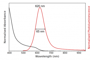
Figure 3: Absorption (black) and photoluminescence (red) spectra of the InP/ZnS QD solution. Absorption parameters: Δλex = 2 nm. Emission parameters: λex = 400 nm, Δλex = 8 nm, Δλem = 3 nm.
In order to confirm the presence of traps, the time response of the photoluminescence was measured using the TCSPC functionality of the FS5; since trap emission and band-edge emission occur on different timescales. A 405 nm picosecond pulsed diode laser (EPL-405) was used to excite the sample and the photoluminescence decay measured as a function of wavelength to build up the time-resolved emission spectrum (TRES) shown in Figure 4. The TRES map clearly shows that the photoluminescence lifetime substantially increases at longer emission wavelengths.
To determine the photoluminescence lifetimes, the decay at the band-edge emission peak (620 nm) and tail emission region (775 nm) were measured with higher temporal resolution and 105 counts at the peak and the decays fit with four exponential components using the FS5’s Fluoracle® software (Figure 5). The band-edge emission peak was found to have an average photoluminescence lifetime of 31.2 ns while the lifetime of the tail emission is 348 ns.
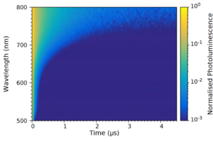
Figure 4: Time-resolved emission spectrum (TRES) of InP/ZnS QD solution measured using TCSPC. The photoluminescence intensity at each wavelength was normalised to 1. Experimental parameters: λex = 405 nm, Δλem = 15 nm.
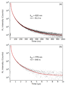
Figure 5: Photoluminescence decays measured at (a) 620 nm and (b) 775 nm. The decays were measured using TCSPC and fit with four exponentials components and the intensity weighted average lifetime calculated. Experimental parameters: λex = 405 nm, λem = 620 nm / 775nm, Δλem = 10 nm.
The fact that tail region decay has an order of magnitude greater lifetime provides further evidence that it is arises due to trapping within the InP/ZnS QDs. A potential mechanism is shown in Figure 6 where electrons at the conduction band edge become trapped at surface defects on the indium phosphide core that have energies within the bandgap. These trapped electrons then slowly radiatively recombine with holes in the valence band, emitting light at a longer wavelength than the band-edge emission. The presence of traps suggests that the ZnS shell may be incomplete and the InP is therefore not fully passivated and that the synthesis procedure should be adjusted to deposit a thicker ZnS shell.
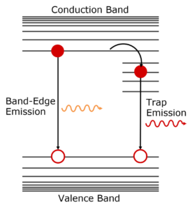
Figure 6: Schematic representation of the origin of band-edge emission and trap emission in QDs.
Conclusion
A combined steady state and time-resolved study of the photophysics of InP/ZnS QDs was carried out using the FS5 Spectrofluorometer revealing the presence of trap emission; possibly due to incomplete ZnS shelling. This application note highlights the capability of the FS5 Spectrofluorometer to characterise the absorbance, emission, and lifetime of novel quantum dot emitters in a single compact instrument and help establish structure-property relationships.
References


