


Avoiding Dead Time Losses with Reverse Mode TCSPC in the FLS1000
TCSPC Overview
Time-correlated single photon counting (TCSPC) is the method of choice for measuring fluorescence lifetimes due to its excellent time-resolution. TCSPC can be thought of as a very fast stopwatch with two inputs (Figure 1). The stopwatch is started by the START signal pulse (the Sync Out from the laser excitation source) and stopped by the STOP signal pulse (detection of a fluorescence photon) and the START-STOP time recorded on a histogram that is stored in memory. Only a single fluorescence photon can be detected during each START-STOP cycle and the process is therefore repeated over millions of cycles to build up the complete histogram of the fluorescence decay. A more detailed description of the principle of TCSPC and the electronics can be found in the Technical Note ‘What is TCSPC?’.
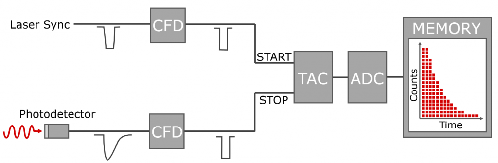
Figure 1: The main components of a TCSPC setup.
Forward Mode & Dead Time
The schematic shown in Figure 1 is known as Forward Mode TCSPC. In Forward Mode, the laser excitation pulse (through the Sync Out trigger of the laser) acts as the START pulse to the TAC (Time-to-Amplitude Converter) and the detection of a photon is the STOP pulse for the TAC. The voltage (which is proportional to the time) on the TAC is then read by the ADC (Analogue-to-Digital Convertor) and stored in memory. After receiving the STOP pulse the ADC takes a finite amount of time to process the event and the TAC must be reset before it can accept the next START pulse. The time to process and reset is known as the ‘dead time’ of the TCSPC electronics, during which the electronics cannot process any subsequent START or STOP pulses. If no STOP pulse is received (because no photon was detected) the TAC must still be reset which also causes a dead time. The pulse sequence of Forward Mode TCSPC and the location of the ADC/TAC dead time is shown in Figure 2.
One of the fundamental principles of TCSPC is that only a single photon can be detected per START pulse period. After detection of a photon (STOP pulse), the system is blind until the next START pulse is received which is marked in yellow in Figure 2. It is important to stress that this not caused by the dead time of the electronics and even in an idealised system with zero dead time, counting of the next photon cannot occur until the TAC has been restarted by a START pulse. If multiple photons arrive later within the same START pulse period only the first photon is counted which results in an artificial skewing of the photon statistics towards shorter times and distortion of the fluorescence decay; an effect called pulse pile-up. To avoid pulse pile-up the probability of multiple photons arriving in a single period must be kept low which is achieved by limiting the photon detection rate to a small fraction of the laser excitation rate; typically no more than 5%. Therefore, only 1 in 20 START periods will on average contain a photon and end with a STOP pulse. In the other 19, the TAC is reset at a user-defined timeout without ever having received a STOP pulse.
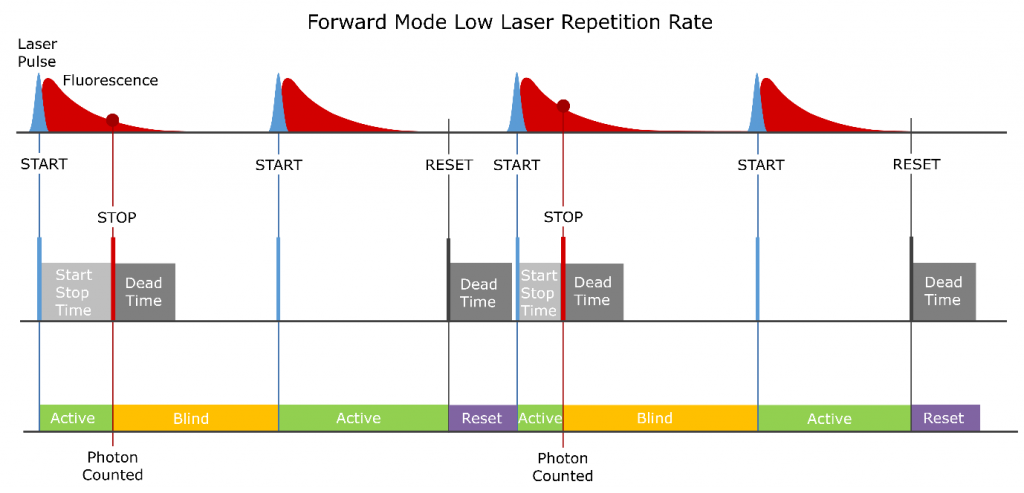
Figure 2: TCSPC operation in Forward Mode with a low laser repetition rate.
The impact that the dead time has on Forward Mode TCSPC depends on the laser repetition rate. At low laser repetition rates, the dead time is significantly shorter than the time between laser (START) pulses which is the situation shown in Figure 2. In this operating regime, the dead time is over before the next START pulse arrives and no photons are lost due to the dead time of the electronics. This is the typical operating condition when measuring many of the most popular materials science samples such perovskite semiconductors and quantum dots which typically have long fluorescence /photoluminescence lifetimes on the order of hundreds of nanoseconds which necessitate that a low laser repetition rate is used.
When measuring samples with shorter fluorescence lifetimes such as organic dyes, increasing the laser repetition rate is advantageous to decrease the time taken to acquire the fluorescence decay. At high laser repetition rates, the dead time can become comparable or even longer than the time between laser pulses which can cause photons to be missed and is illustrated in Figure 3. In this operating regime, START pulses may arrive during the dead time which causes entire START periods to be skipped by the electronics. Any photons that arrive during these skipped periods are not counted by the electronics and the time taken to acquire the fluorescence decay is increased. To avoid dead time losses at high laser repetition rates, the TCC2 counting electronics module used in the FLS1000 can be operated in Reverse Mode.
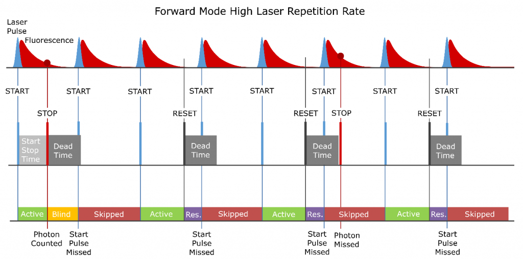
Figure 3: TCSPC operation in Forward Mode with a high laser repetition rate resulting in dead time induced photon counting losses.
Avoiding Dead Time Losses with Reverse Mode
The Forward Mode TCSPC operation shown in Figure 3 is inherently inefficient as the electronics are spending the majority of their time responding to START pulses that have no associated STOP pulse. As explained earlier, the photon detection rate is always kept <5% of the laser repetition rate to prevent pulse pile-up and the TAC is therefore being started 20 times more often than actually required to detect the photons. Reverse Mode TCSPC takes advantage of the lower photon detection rate by swapping the START and STOP inputs as shown in Figure 4.
In Reverse Mode the detection of a photon now provides the START pulse for the TAC and an electrically delayed pulse from the laser provides the STOP. The great advantage of this configuration is that the TAC is only started when a photon is present and unnecessary TAC resets are avoided. A dead time in the electronics now only occurs after the detection of a photon and the overall time that the electronics spend in dead time is reduced by a factor of 20 or more. The dead time, therefore, has a much lower impact on the acquisition time in Reverse Mode; and dead time counting losses are negligible in Reverse Mode for many fluorescent samples.
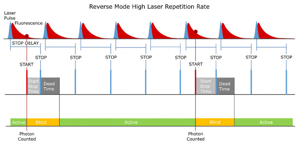
Figure 4: TCSPC operation in Reverse Mode with a high laser repetition rate.
Rapid Forward Reverse Mode Switching
Given the advantage of Reverse Mode one question that could be asked is, why isn’t Reverse Mode used for all TCSPC measurements? The primary reason is the length of the delay required for the STOP pulse. When measuring long fluorescence lifetimes at low laser repetition rates a very long delay is required to get the STOP to arrive at the correct position; usually requiring an external delay line to be inserted between the laser and the TCSPC electronics. This is impractical to implement and combined with the fact that Reverse Mode gives no advantage at low laser repetition rates means that Forward Mode is the operating mode of choice for long fluorescence lifetimes.
The software and hardware of the FLS1000 have been carefully designed for easy switching between the Forward and Reverse Modes with a single button press in the Fluoracle operating software. No cable or connection changes are required and all delays required for Reverse Mode operation can be configured within the software. The enables the user to quickly switch between Forward Mode for long lifetime samples where dead time is not an issue, and Reverse Mode for short lifetime samples to avoid dead time losses.
