


LP980 Transient Absorption Spectrometer Diffuse Reflection Accessory; Alignment and Example Measurements of Benzil Powder
Introduction
Understanding photogenerated excited electronic states, light mediated chemical reactions and intermediates, and photo driven energy or electron transfers is paramount to designing and developing the next generation of materials from therapeutics to solar cells. Having the ability to measure these processes in the solid state (powder, film, glass) further enables researchers to glean vital photoinduced electronic properties of their materials and devices in their real-world application uses. The Edinburgh Instruments LP980 Transient Absorption Spectrometer, equipped with the diffuse reflection accessory, is engineered to measure excited state lifetimes and spectra from nanoseconds to seconds, and is the world’s only transient absorption spectrometer to feature a pulsed flashlamp as a high-intensity, ultra-stable probe source, and a dual detector measurement mode offering both an ICCD camera for time-gated transient spectra and a PMT for kinetic transient lifetimes.
Figure 1: The Edinburgh Instruments LP980 Spectrometer.
To ensure the highest level of sensitivity in any transient absorption measurement, it is imperative that first, the probe beam (lamp) is optimally aligned to the input of the monochromator or spectrograph so that as much light as possible reaches the detectors. Then, that the pump beam (laser) is overlapping the probe beam in the sample to get the most transient signal. This document is written to show our customers how to properly align and measure solid samples using the LP980 Transient Absorption Spectrometer when equipped with the diffuse reflection accessory. Your Edinburgh Instruments support engineer or technical specialist will teach you how to do this during the installation or through live video support after purchase.
Tools and Samples Required
Before getting started, you will require a set of metric Allen (hex) wrenches, appropriate laser safety goggles, and another person from your lab; they will be needed to help you over-ride the laser-safety interlocks for final adjustments. Please prepare a sample of Benzil powder (Aldrich-B5151) in the included powder sample holder (Figure 2.), and have a white business card nearby.
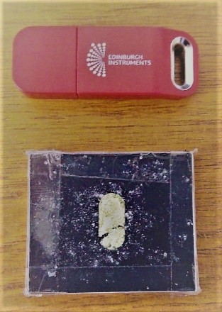
Figure 2: The diffuse reflection powder sample holder filled with Benzil powder (USB drive shown for size comparison).
Procedure
Before changing the sample stages to those utilised for the diffuse reflection accessory, please ensure the LP980 is fully aligned and optimally working; this will make it easier to align the diffuse reflection sampling mirrors and steer the laser to the correct position using the internal laser steering prisms and mirrors. You can refer to our LP980 alignment technical note for the proper procedure our team uses. Also, ensure the laser’s power is much lower relative to when measuring samples in the solution phase; the high energy pulses can easily damage and burn samples when not buffered by solvent.
The dual diffuse reflection accessory is a two-part module for measuring opaque samples that utilises both positions in the sample chamber. These may be powder samples but glass and film samples can also be measured if they have an opaque backing. It can also be used for highly concentrated solution samples in a front-face configuration that have a significant scattering potential. The positioning of the components is shown in Figure 3, with the light paths of the laser and probe lamp. To begin the alignment procedure, it is useful to have a piece of a white business card in the sample position to easily see the beams.
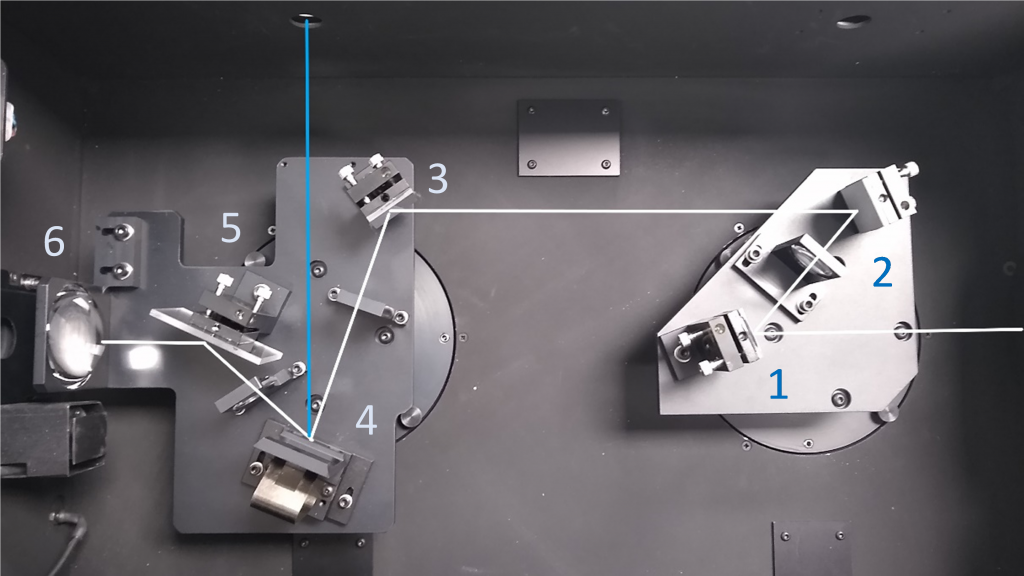
Figure 3: The optical layout and positioning of the diffuse reflection accessory in the LP980 sample chamber. Before starting, the laser should be roughly aligned such that is passes through the cuvette sample holder’s back-end hole. Please contact your Edinburgh Instruments engineer for any questions.
Step 1: Probe (Lamp) and Pump (Laser) Alignment
Once you and your lab partner are ready to begin, run L900 software and make sure everything starts normally. You will only need to use the PMT detector for these alignments. On the back of the PMT detector box, please set the PMT Bias Voltage Dial to ‘7’, and also ensure the impedance selector is in High Bandwidth Mode. Place a white business card with writing on it in the sample position. The lamp lid and laser lid should be closed; however, you will need the lid for the sample area off so you can see both sample positions (Figure 3.).
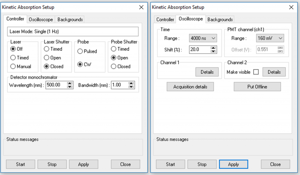
Figure 4: Kinetic absorption Setup settings for probe beam alignment.
Click on the kinetic absorption button and launch the setup window (Figure 4). In the controller tab, set; laser=off, laser shutter=closed, probe=CW, probe shutter=open, wavelength=500 nm, and band-width=1nm. In the Oscilloscope window, set time range=4000 ns, voltage=160 mV, shift=20%; then click Apply and you should see the probe lamp entering the sample chamber.
The path for the probe light is shown in white in Figure 3. Use the mirror-1 on the right-side module to direct the light through the lens onto the mirror-2, and then adjust the mirror-2 to direct the probe light onto mirror-3 on the left-side module. In turn, adjust mirror-3 to direct the light through the lens onto the business card in the sampling position-4. There may be some iterative adjustment of the mirrors to get the light centred on all of them. The lens on the right-side module between mirror-1 and mirror-2 is adjustable to improve the focus of the lamp image on the card. At this point, you should see the light reflecting off the business card, hitting mirror-5 and then to collection optic-6 with light being focused to the bronze slit behind the shutter; you can have your lab partner open the shutter by engaging the 2 interlocks to open the monochromator shutter. If everything is aligned, you can see an image of the writing on the business where the probe lamp is hitting it being centred on the focusing optic-6 before the monochromator, and you can adjust mirror-5 after the sample to ensure this alignment.
Next, set the probe shutter=timed (keep all other settings), click Apply and then Start; you will see the probe shutter opening and closing and zero signal. Here again, please ask your other lab person to override the interlocks on the sample chamber by pressing on the two silver buttons on the lid’s edge. At this point, you should see the light pulsing off the business card, hitting the collection optic, and then being focused to the slit. Adjust the final mirror(s) next to the sample to achieve the highest possible signal level in mV. If no signal is seen, check that the lamp light is focused on the slit entering the monochromator and adjust the mirror(s) coarsely so that light is entering the monochromator, then resume fine alignment as noted above. Once you achieve the highest signal, stop the measurement.
Now set laser=timed, laser shutter=timed, probe=CW, probe shutter=open, wavelength=500 nm, and bandwidth=1 nm. In the Oscilloscope window, set time range=4000 ns, voltage=160 mV, shift=20% as before.
Do not override the interlocks during this step.
Click Apply, then Start; your laser will begin pulsing and you should see the laser beam pulse over the top of your lamp’s probe beam. If not, adjust the laser alignment so that it overlaps the probe beam. Once the overlap is achieved, stop the measurement.
Step 2: Standard Sample Verification
A suitable sample for verifying the positioning of the accessory is Benzil (Aldrich-B5151). The powder should be placed in the dedicated sample cuvette and sealed so that it does not spill when placed vertically in the sample holder. The sample responds to laser 355 nm excitation and produces a relatively strong signal at 470 nm.
Replace all lids and ensure they are closed and engaging the interlocks. Click on the kinetic absorption button and launch the setup window again. In the controller tab, set; laser=timed, laser shutter=timed, probe=pulsed, probe shutter=timed, and wavelength=470 nm, and start with the bandwidth=1 nm. In the Oscilloscope window, set time range= 200 µs, voltage=160 mV, shift=20%. Click Apply, and Start; adjust the bandwidth so that the signal is optimized to be as high as possible without going over 600 mV.
Next, go to the Kinetic Multiple tab to make a measurement. In the background tab, ensure both probe and fluorescence backgrounds are checked; you should be able to see the 3 traces as can be seen in Figure 5. The fluorescence correction will also help remove any fast fluorescence and laser scatter. The resultant delta OD trace is seen in Figure 5.
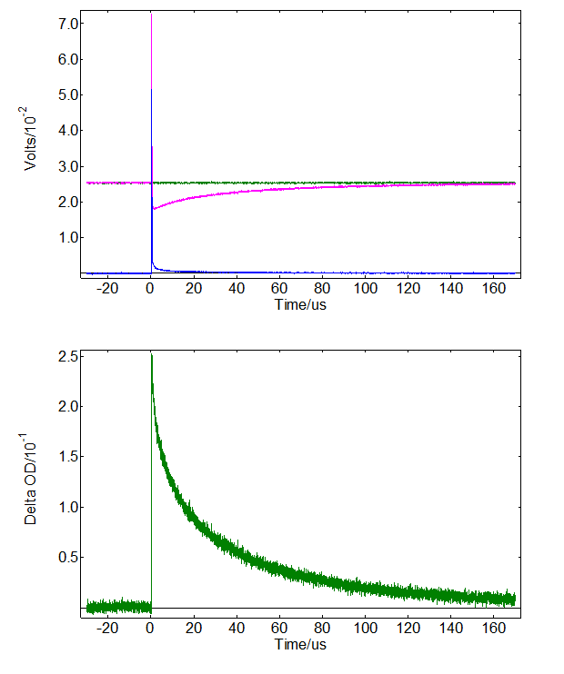
Figure 5: (Top) Raw data of the transient absorption signal of Benzil powder with probe and fluorescence backgrounds turned on, and the resulting transient signal acquired at 470 nm.
Your system is now aligned and ready for use; please place your sample and follow good practices for measuring.
Download the Technical Note
You can download the complete Technical Note: LP980 Transient Absorption Spectrometer Diffuse Reflection Accessory; Alignment and Example Measurements of Benzil Powder
