


Measuring Charge Carrier Lifetime in Perovskite Solar Cell Materials Using Time-Resolved Photoluminescence Spectroscopy
Halide perovskite solar cells have attracted tremendous attention over recent years due to the rapid rise in solar cell efficiencies and their potential for providing high efficiency low cost solar power. Perovskite solar cell efficiencies have increased from 9% in 2012 to 21% in 2017 and are now competitive with traditional crystalline silicon cells. Despite this impressive rise in efficiency, the fundamental physics of these materials is not yet fully understood. The lifetime of the charge carriers plays an important role in determining the efficiency of the cell, as longer lived carriers will have a higher probability of reaching the electrodes. In efficient solar cells the charge carriers combine radiatively, which makes time-resolved photoluminescence spectroscopy a powerful tool to monitor the charge carrier lifetime and further the understanding of perovskite solar cells. In this application note time-resolved photoluminescence spectroscopy will be shown to be a powerful tool for investigating and optimising the behaviour of the perovskite solar cell material methyl ammonium lead iodide by measuring the influence of annealing on its charge carrier lifetime.
Named after the Russian mineralogist Lev Perovski, the term perovskite refers to any compound which has an ABX3 crystal structure. However, in the context of photovoltaics, perovskite refers specifically to a small group of methylammonium metal halides which are promising photovoltaic materials due to their low cost, solution processability and high efficiency. The most widely studied and thus far most promising of these materials is methylammonium lead iodide (CH3NH3PbI3) or MAPI for short, the crystal structure of which is shown in
Figure 2a.
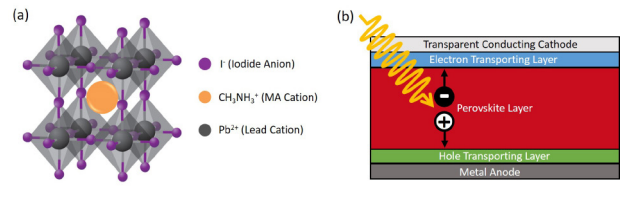
Figure 2: (a) The crystal structure of MAPI perovskite. Image adapted from Cui et al.3 (b) A typical MAPI perovskite photovoltaic cell structure.
The design of a typical MAPI perovskite photovoltaic cell is shown in Figure 2b. The perovskite layer is sandwiched between electron and hole transport layers and two collection electrodes; one of which must be semi-transparent. During operation an incoming photon passes through the semitransparent electrode and is absorbed by the perovskite layer, which creates a free electron and hole in the material.
The electron and hole (charge carriers) then diffuse towards the cathode and anode respectively, before being collectedto generate an electrical current. The greater the number of charge carriers that reach their respective electrodes before undergoing recombination, the higher the efficiency of the cell. The lifetime of the charge carriers therefore plays an important role in determining the efficiency of the cell, as longer lived carriers will have a higher probability of reaching the electrodes. In efficient photovoltaic cells the charge carriers combine radiatively, which makes time-resolved photoluminescence spectroscopy a powerful tool to monitor the charge carrier lifetime and further the understanding of perovskite photovoltaic cells.
Methods and Materials
MAPI perovskite films were deposited on quartz discs, using the methylamine / acetonitrile route developed by Noel et al.4
After deposition of the perovskite, the films were annealed on a hotplate at 100 °C. A layer of the fluoropolymer CYTOP was then spin coated on top of the perovskite layer to serve as a moisture barrier.
Photoluminescence emission spectra and absorption spectra were measured on an FLS1000 Photoluminescence Spectrometer equipped with double monochromators, a 450 W Xenon lamp, EPL-405 pulsed diode laser, a PMT-900 detector and the N-F02 absorption accessory. The perovskite coated quartz discs were positioned using the N-J03 frontface sample holder.
Results and Discussion
The absorption and photoluminescence emission (PL) spectra of a MAPI perovskite film are shown in Figure 3. From the
onset of absorption (~770 nm) the bandgap of MAPI can be estimated to be approximately 1.6 eV which is in agreement with previous surface photovoltage measurements.5 The PL spectrum of MAPI consists of a narrow peak centred on 780 nm which corresponds to band-to-band recombination of electrons in the conduction band with holes in the valence band.
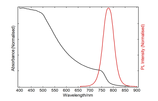
Figure 3: Absorption (black) and photoluminescence emission (red) spectra of a MAPI perovskite thin film. The absorption spectrum was measured using the N-F02 absorption accessory. The PL and absorption spectra were measured using the Xenon lamp for excitation. The excitation wavelength for the PL spectrum was 500 nm.
The PL decay of the MAPI film was measured using timecorrelated single photon counting (TCSPC) at the peak of the PL emission (780 nm) and is shown in Figure 4.
MAPI is not a completely homogenous material and exhibits a complex microstructure, which results in the charge carrier recombination rate spatially varying over a nanometre length scale.6 The PL decay therefore does not have a single well defined decay constant and cannot be fit using simple exponentials. Instead, perovskite PL decays are commonly fit using stretched exponentials which better describe the distribution of recombination rates that are present.4,7
Edinburgh Instruments offers the FAST software package for analysing complex decays. FAST provides several analysis options such as Förster kinetics, time-resolved anisotropy and global exponential analysis in addition to the stretched exponential analysis used here. A stretched exponential decay has the form,
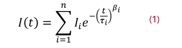
where I(t) is the fluorescence intensity at time t, n is the number of components, Ii is the initial intensity of each component, τi is the characteristic lifetime and βi is the stretching exponent (0<βi ≤1). β deforms the exponential so that the initial decay is faster and the tail longer. The lower the value of β the greater the deformation, while a β of 1 corresponds to a pure exponential decay. FAST can fit decays with up to four (n=4) stretched exponential components. The PL decay in Figure 4 was fit using a two-component stretched exponential (stretched biexponential, n=2) which is shown by the red line.
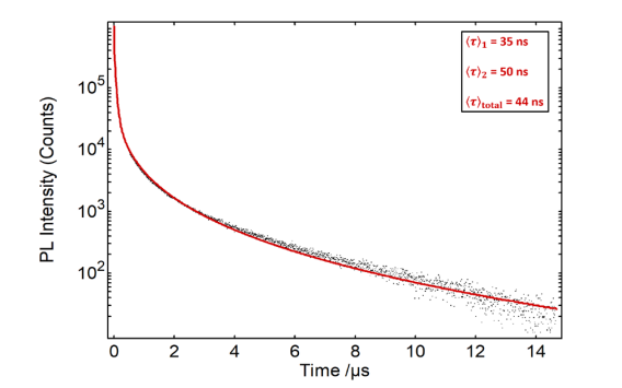
Figure 4: PL decay of MAPI perovskite thin film measured using TCSPC (black) and fit using a two component stretched exponential (red). The mean lifetime of each stretched exponential was determined using Eq. 2 and the total weighted mean calculated. Excitation source = EPL-405 pulsed diode laser, Rep Rate = 100 kHz, λem = 780 nm, Δλem = 10 nm.
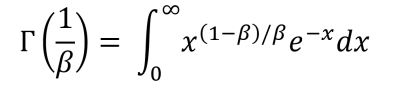
The lifetime of a stretched exponential decay is best quantified by its mean relaxation time 〈τ〉 which is given by,7,8
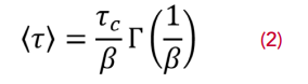
where Γ(1/β) is the gamma function,7,8
The mean relaxation time of the two components of the stretched exponential were calculated using Eq. 2 to be 〈τ〉1 = 35 ns and 〈τ〉2 = 50 ns with the total weighted mean, 〈τ〉 total, of the two components being 44 ns.
During cell fabrication, the perovskite layer is deposited by spin-coating and the layer is then normally annealed at a high temperature to complete the formation process. The temperature and duration of this annealing step can have a dramatic impact on the microstructure of the perovskite layer and on the efficiency of the photovoltaic cell. The PL decay shown in Figure 4 was measured on a MAPI film that had been annealed for 60 minutes at 100 °C. In Figure 5 the PL decay from this film is compared to two other MAPI films that were fabricated using different annealing times. Figure 5 shows that as the annealing time is increased from 15 minutes to 60 minutes the mean lifetime of the PL decay increases from 28 ns to 44 ns which demonstrates that annealing the film for longer increases the lifetime of the charge carriers and may improve cell efficiency. This highlights the potential of timeresolved photoluminescence spectroscopy for understanding the influence of annealing on the microstructure and efficiency of perovskite photovoltaic cells.
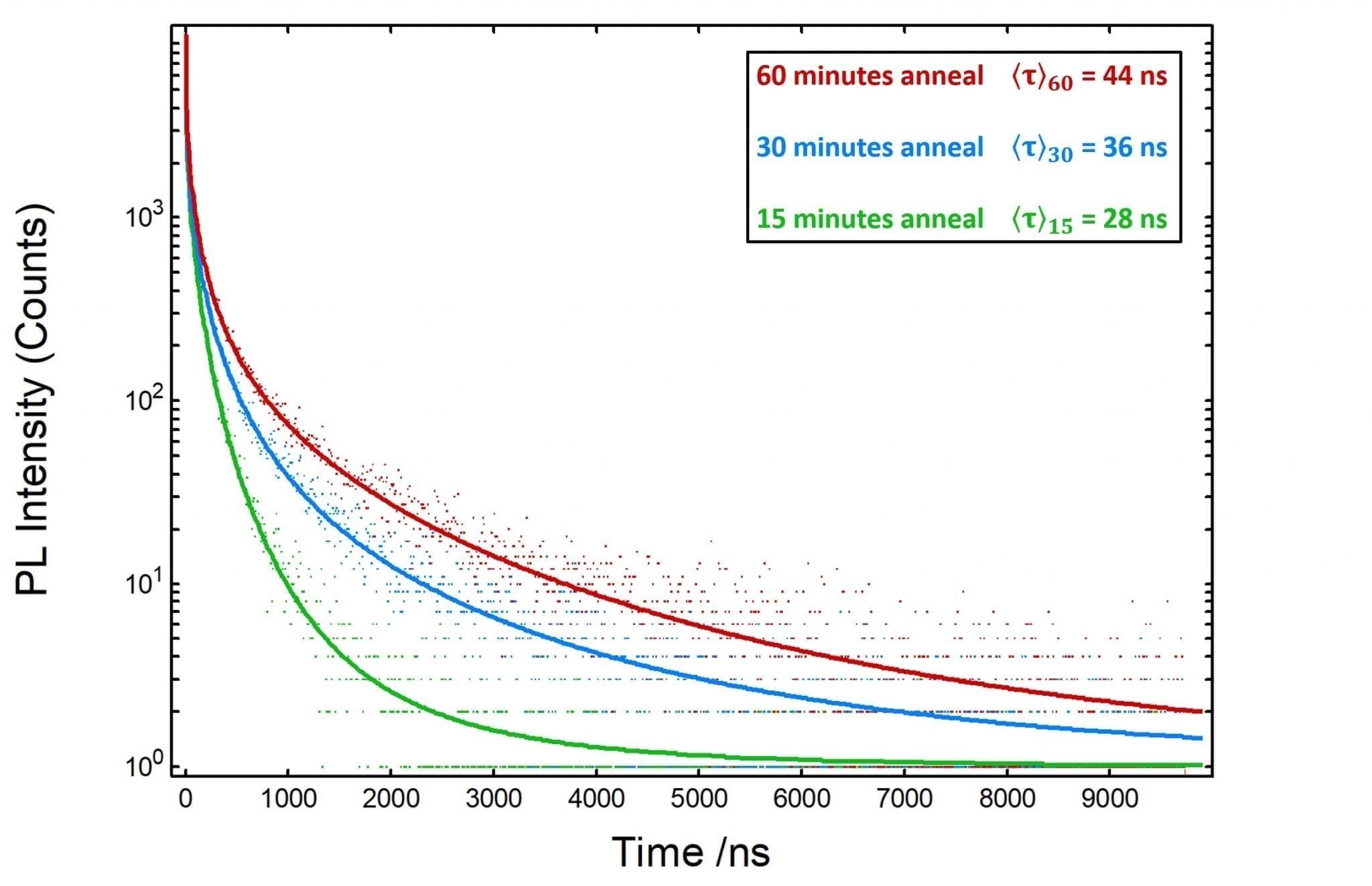
Figure 5: PL decay of three MAPI perovskite thin film that were annealed for 15, 30 and 60 minutes at 100 °C and measured using TCSPC. The PL decays were fit with two component stretched exponentials and the weighted mean lifetime calculated. Excitation source = EPL-405 pulsed diode laser, Rep Rate = 100 kHz, λem = 780 nm, Δλem = 10 nm.
Conclusion
The charge carrier lifetime of MAPI perovskite films was measured using time-resolved photoluminescence spectroscopy with an FLS1000 Photoluminescence Spectrometer. The decay kinetics were fit with stretched exponentials using the FAST software package. The influence of annealing on the carrier lifetime was investigated by measuring the PL decay of perovskite films fabricated with different annealing times. The mean lifetime of the PL decay was found to increase with annealing time, indicating that longer annealing extends the average charge carrier lifetime which may improve photovoltaic efficiency. This study highlights the potential of time-resolved photoluminescence
spectroscopy for understanding the physics and improving the efficiency of perovskite photovoltaic cells.
Download Full Application Note
Sign-Up for our Application and Technical Notes
If you have enjoyed reading our Application Note, why note sign-up to our infrequent newsletter via our red Sign-up button below.
