Radioluminescence is the emission of UV or visible light from a substance (luminescence) upon excitation from high-energy, ionising radiation.1 This includes X-rays, gamma-rays, α-particles (Helium nuclei), β-particles (electrons) and other high-energy particles. Scintillation and Cherenkov radiation are types of radioluminescence.2
Radioluminescence is not typically used to describe the process of X-ray fluorescence (XRF). This is because XRF is an “X-ray in, X-ray out” technique, whereas radioluminescence is “X-ray in, UV/visible out”.
The term scintillation is often used interchangeably with radioluminescence and describes the emission of UV or visible light upon excitation from ionising radiation or radioactive particles. Scintillation is measured using a technique known as X-ray excited optical luminescence (XEOL).3
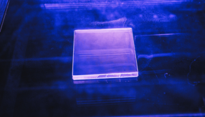
Substances that exhibit this behaviour are called scintillators or phosphors. Historically, the term phosphor has also been used to describe any substance that is luminescent. For clarity, we will use the term scintillator. Materials capable of scintillation include inorganic crystals, organic crystals, noble gases, and plastic scintillators (Figure 1). Examples of these will be discussed below.
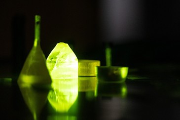
Figure 1: A selection of inorganic scintillator crystals. Credit: René Volfík – Institute of Physics of the Czech Academy of Sciences. Reproduced under CC BY-SA 4.0 licence.
The mechanism of scintillation is dependent on the type of material and the energy of the excitation radiation. The most widely-used class of scintillators are inorganic crystals, such as thallium-doped caesium iodide (CsI:Tl). For materials like these, scintillation occurs over three stages: conversion, energy transfer, and luminescence.
Conversion
This process is the interaction of incident radiation with a scintillator to generate charge carriers, electrons (e–) and positive holes (+). The mechanism of this process depends on the energy of the incident radiation 4:
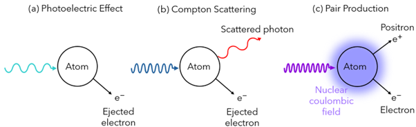
Figure 2: The three processes involved in conversion of ionising radiation into charge carriers: (a) The photoelectric effect, (b) Compton scattering, and (c) pair production.
These three processes generate high-energy electrons, which in turn cause secondary processes resulting in the formation of many electron-hole pairs. Understanding how this results in the formation of UV and visible light requires a basic understanding of the band theory of solids. In this theory, scintillators are classed as insulators, as they possess a large band gap (>5 eV). This is the difference in energy between their filled, lower-energy valence band, and their unfilled, higher-energy conduction band.
Incidence with ionising radiation causes electrons to be excited beyond the conduction band, leaving a positive hole in the valence band. These high-energy electrons undergo “thermalisation”, whereby they lose energy as heat to reside in the conduction band (Figure 3).5
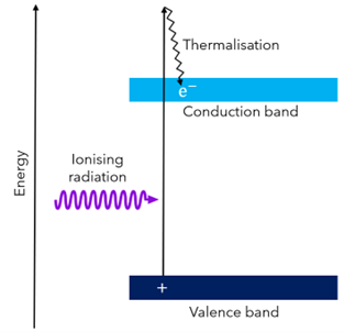
Figure 3: Energy level diagram of a scintillator during the conversion process. Ionising radiation excites an electron (e–) from the valence band to above the conduction band, where it loses energy as heat (thermalisation). Excitation of the electron leaves a positive hole (+) in the valence band.
Energy transfer
During this process, electrons and holes in the conduction and valence bands, respectively, migrate through the material until they reach a luminescence centre or activator. These are crystal defects or dopants purposely introduced into the scintillator which possess energy levels that reside between the conduction and valence bands. An example of activators are the thallium ions doped into caesium iodide. The electrons and holes transition from the conduction and valence bands to occupy the activator’s excited and ground states, respectively (Figure 4). 6
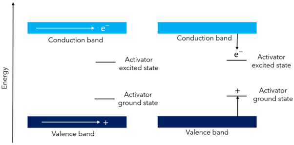
Figure 4: Energy level diagram of a scintillator showing the energy transfer process. Electrons and holes migrate through the scintillator to an activator, whereby they occupy their excited and ground states respectively.
Luminescence
Finally, the electron and hole recombine, releasing light (Figure 5). As the difference in energy between the excited and ground states of the activator is sufficiently small, the light produced is in the UV or visible range rather than as another form of ionising radiation.
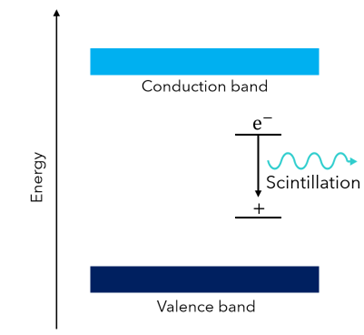
Figure 5: Energy level diagram of a scintillator showing the luminescence process. Electrons and holes occupying the activator energy levels recombine releasing energy as UV/Visible light.
Scintillators are used for sensing ionising radiation by its conversion to lower energy UV/Visible light, which is more easily detected and quantified. This is typically done by a photomultiplier tube (PMT) detector. Detection of ionising radiation is important for several applications7:
The most common classes of scintillators include inorganic crystals, organic crystals, and plastic scintillators. They are characterised by their density, decay time, and light output (quoted as a percentage of a reference scintillator, commonly anthracene). Good scintillators will have a high light output, a short decay time (more responsive radiation detector), and are chemically and mechanically robust. Most scintillators tend to emit in the blue region of the visible spectrum (350-450 nm), but any colour may be emitted if a chemical known as a wavelength shifter is included in its composition. The shifter absorbs the shorter wavelength light emitted by the scintillator, and emits it at a longer wavelength through traditional fluorescence.
Some of the most widely-used scintillators, their properties, and applications are shown in Table 1.
Table 1: The properties and applications of popular scintillators. 8
| Material type | Light output (% Anthracene) | Decay time (ns) | Applications | |
|---|---|---|---|---|
| NaI:Tl | Inorganic Crystal | 230 | 230 | Environmental radiation detector |
| CsI:Tl | Inorganic Crystal | 300 | 600 | Detector in baggage scanners |
| Bismuth Germinate (BGO) | Inorganic Crystal | 40 | 350 | PET imaging, Compton shields |
| PbWO4 | Inorganic Crystal | 2.5 | 5–15 | PET imaging, detectors in particle physics |
| Anthracene | Organic Crystal | 100 | 30 | CT imaging |
| Trans-Stilbene | Organic Crystal | 50 | 4.5 | Fast neutron detectors |
| p-Terphenyl | Liquid solution or solid plastic | 58 | 5 | Fast neutron detectors |
| 2,5-Diphenyl oxazole (PPO) | Liquid solution or solid plastic | 50 | 1-5 | Neutron detectors |
Current research into scintillators focuses on making stable materials with short decay times and high light outputs. At Edinburgh Instruments, we have produced the XS1 Radioluminescence Chamber for this purpose. When combined with our FLS1000 or FS5 Spectrometers, the XS1 allows for spectral and time-resolved radioluminescence measurements for optical characterisation of scintillators. You can find out more about the XS1 and how it could advance your research into radioluminescent materials, visit our XS1 product page.
As well as scintillation, radioluminescence also describes the production of Vavilov–Cherenkov radiation, or Cherenkov radiation for short.
Cherenkov radiation is released when a charged particle travels faster than light in a dielectric medium (a substance that can be electrically polarised).9 One of the fundamental laws of physics is that nothing travels faster than light in a vacuum. However, in a medium such as water, light slows down, and high-energy particles are able to travel faster. The most famous example of Cherenkov radiation is the distinctive blue glow of underwater nuclear reactors caused by the emittance of high-energy charged particles (Figure 6).
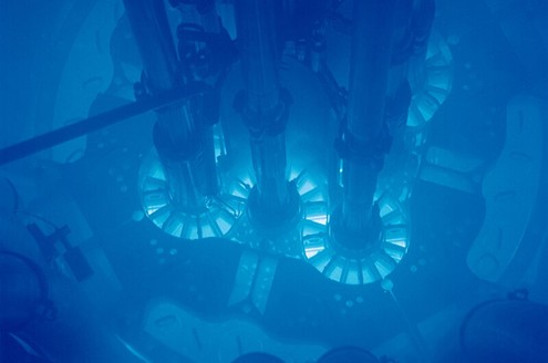
Figure 6: Emission of blue Cherenkov radiation from an underwater nuclear reactor at the Idaho National Laboratory. Credit: Argonne National Lab, reproduced under CC-2.0 licence.
When charged particles move through a dielectric medium, they alter nearby atoms of that medium. For example, when a negatively-charged electron passes through a dielectric medium, it will repel negatively-charged electrons of atoms and attract the positively-charged nuclei. This is called polarisation and it is a higher-energy state compared to the medium at equilibrium.
As the charged particle moves away, the polarised atoms relax back into their depolarised state and release the energy in the form of a series of spherical light waves. At lower speeds, this occurs symmetrically, and the light waves never touch each other (Figure 7a). However, at higher speeds, the light waves are generated faster than they can move away from each other, and they overlap (Figure 7b). This overlap results in constructive interference of the light waves forming a cone of UV/visible light behind the particle (in the same way a boat leaves a V-shaped wake behind it, but in three dimensions).10
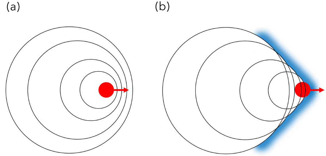
Figure 7: A charged particle (red) moving through a dielectric medium as light waves are emitted (black). (a) When the particle moves slower than the speed of light in the medium, the light waves do not overlap. (b) When the particle moves faster than the speed of light in the medium, the light waves overlap, forming a cone of Cherenkov radiation (represented here as a 2D V-shape).
This is the same principle behind a shock wave, where a plane moving faster than the speed of sound causes sound waves to interfere, amplifying them into a loud sonic boom.
Overall, radioluminescence is a fascinating and constantly evolving area of study. It has important applications from medical imaging to fundamental physics research. You can find out more about how the XS1 and other Edinburgh Instruments products can help achieve your spectroscopy aims, by speaking to our friendly team.