Circularly polarised luminescence (CPL) spectroscopy is a powerful technique that exploits the differential emission of left- and right-circularly polarised light from chiral structures (Figure 1).1 By analysing the polarisation state of the emitted luminescence, researchers can gain detailed information about the electronic transitions, molecular symmetry, and stereochemistry of the sample. This technique has proven invaluable in studying a wide range of chiral systems, including organic compounds, inorganic complexes, and biomolecules.
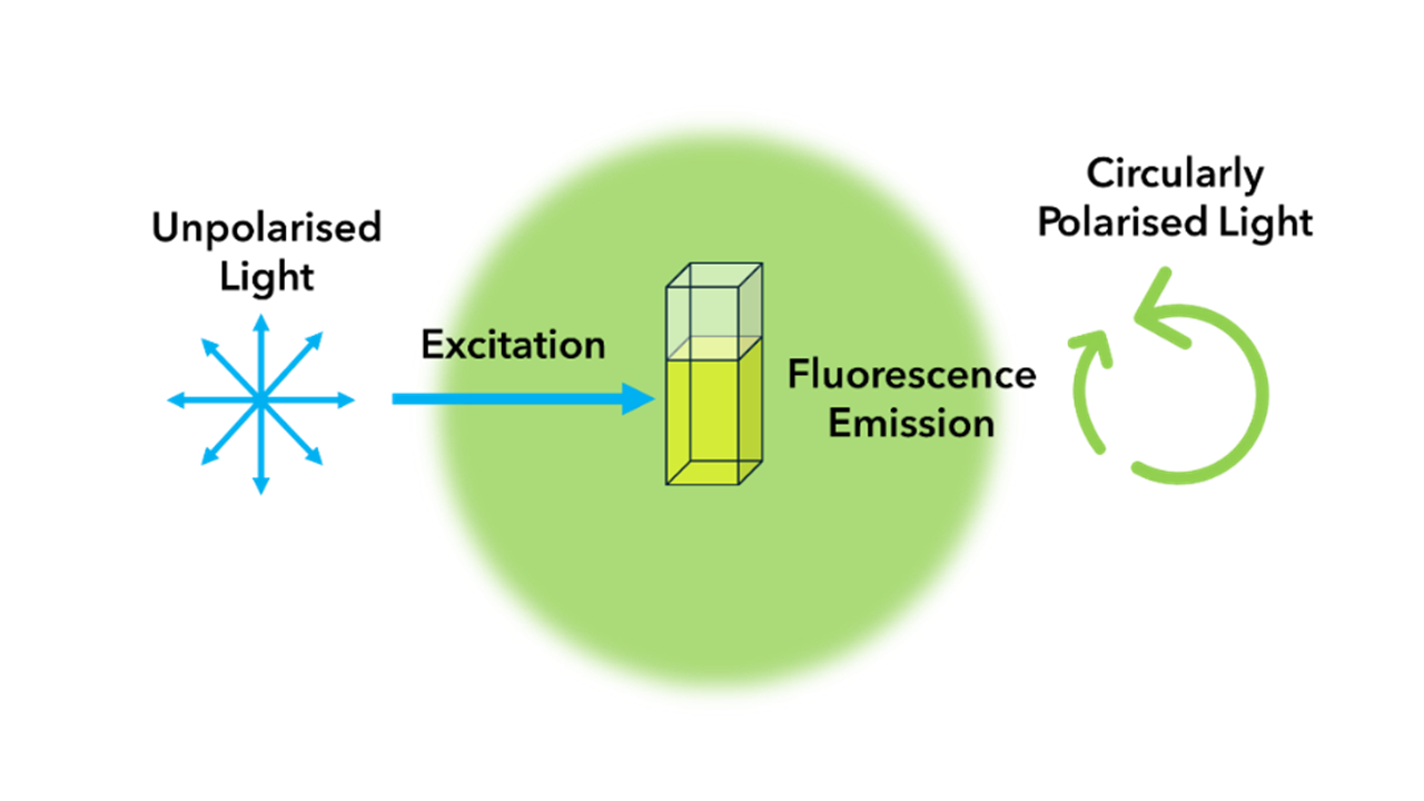
Figure 1. The principles of Circularly Polarised Luminescence (CPL).
CPL spectroscopy is a specialised technique that is applicable only to chiral systems. Chiral structures possess a non-superimposable mirror image, known as enantiomers. Enantiomers can emit different amounts of left- and right-circularly polarised light, making them detectable by CPL spectroscopy.
CPL spectroscopy relies on measuring circularly polarised light emitted from a sample. Circularly polarised light is composed of two perpendicular plane waves of equal amplitude that differ in phase by 90º, which equates to one quarter wavelength. The resulting electric field rotates in a circle around the direction of propagation (Figure 2). Circularly polarised light differs from linear polarised light where the light wave oscillates in only a single plane.

Figure 2. Circularly polarised light is composed of two perpendicular waves of equal amplitude that differ in phase by 90º. The electric field rotates in a circle around the direction of propagation (blue arrows).
Light can also be elliptically polarised, which is generally the case in CPL because the total luminescence emission from a sample is a mixture of left and right-handed polarised light (Figure 3). Elliptically polarised light has two perpendicular waves which are out of phase which is the same as circularly polarised light. However, unlike circularly polarised light, the amplitude of the waves in elliptically polarised light is unequal or they are not out of phase by exactly 90º.
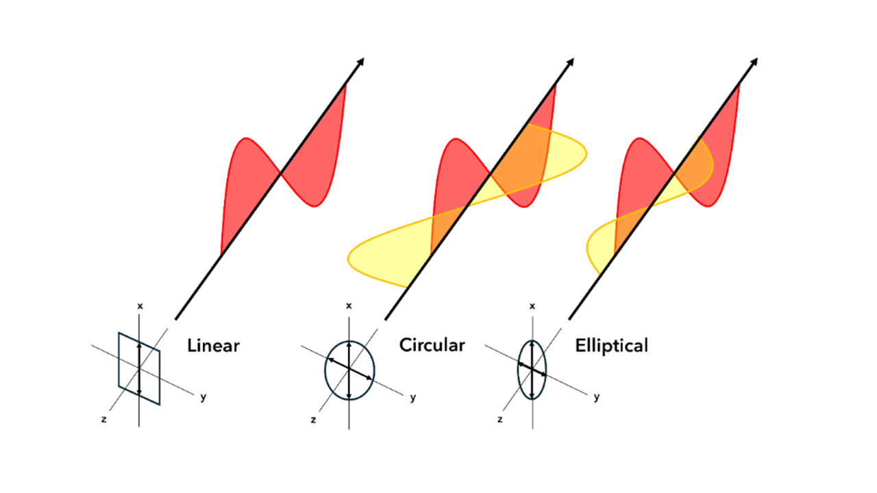
Figure 3. Linear, circular and elliptical polarisation of light. Arrows on axes show the direction of light propagation which is perpendicular to the electric field oscillation.
In elliptical or circularly polarised light, the electric field vector of the light rotates clockwise or anti-clockwise as it propagates, thus the polarised light can be left or right-handed depending on the direction of the helical path.
To determine if circularly polarised light is left- or right-handed you must imagine the direction of rotation from a fixed point of view, for example that of the light source. From the point of view of the light source, a clockwise rotation indicates a right-handed circularly polarised wave, and an anticlockwise rotation indicates a left-handed wave. Figure 4 shows the electric field vector of light propagating in a helix shaped path, in this image the direction of light propagation is from left to right (indicated by central arrow). From the point of view of the light source, this is right-handed (clockwise) circular polarisation.
Figure 4. Electric field vector of a travelling circularly polarised electromagnetic wave. This depicts a wave in the right-handed/clockwise circular polarisation state as defined from the point of view of the source.
To help visualise the handedness of circular polarisation, make a thumbs up with your hand and point your thumb in the direction of wave propagation. The direction in which the rest of your fingers curl is the direction in which the polarisation vector travels. This direction will be different for each hand. Figure 5 illustrates the difference between left- and right-handed circular polarisation.
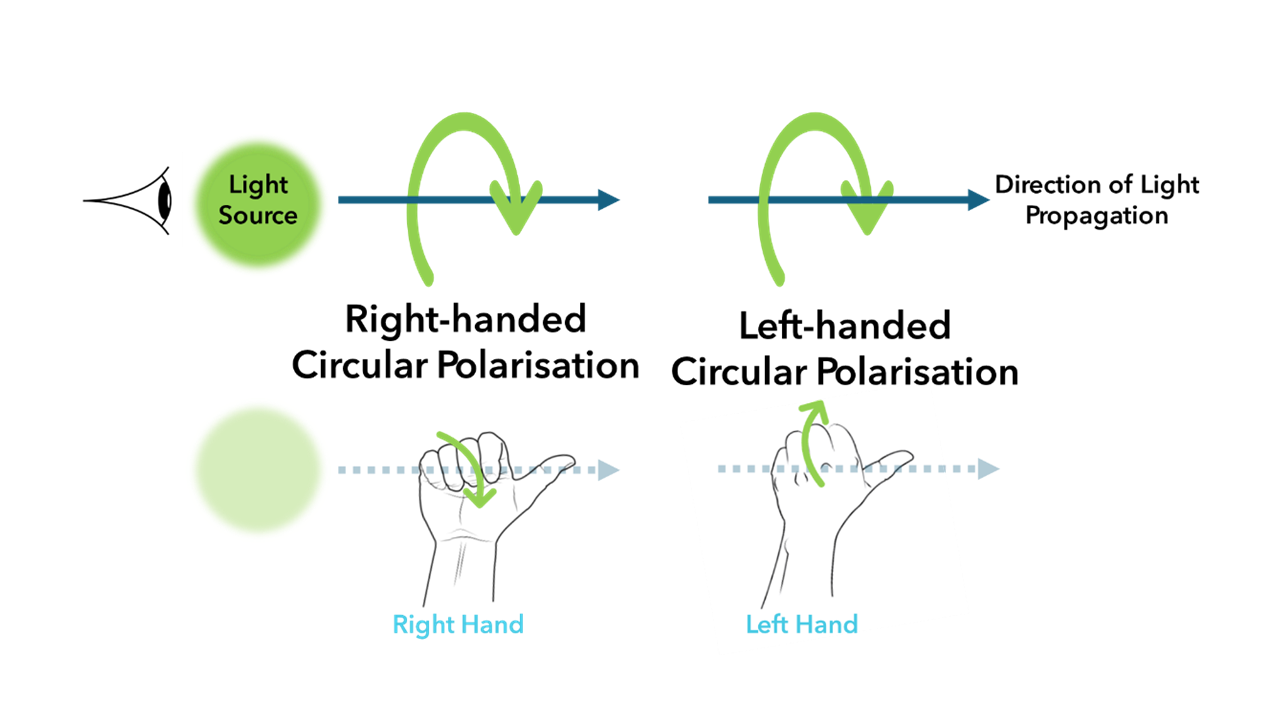
Figure 5. Left- versus right-handed circular polarisation.
CPL arises from the interplay between the electronic and magnetic properties of chiral structures.2 The inherent asymmetry of chiral materials influences the orientation of the electric and magnetic dipole moment.
The electric dipole represents the separation of positive and negative charges within a molecule. The magnetic transition dipole arises from the motion of electrons within the molecule, creating a localised magnetic field.
When these dipoles are aligned in a specific orientation relative to each other, the emitted light becomes circularly polarised.
The specific alignment of these dipoles is determined by the chiral structure of the material and the nature of the electronic transitions involved in the luminescence process.
While samples often exhibit bright luminescence, CPL spectroscopy can be challenging due to samples exhibiting weak CPL behaviour. This is because the difference between left- and right-handed circularly polarised light is small, requiring sensitive detection. Figure 6 illustrates the steps involved in measuring CPL.
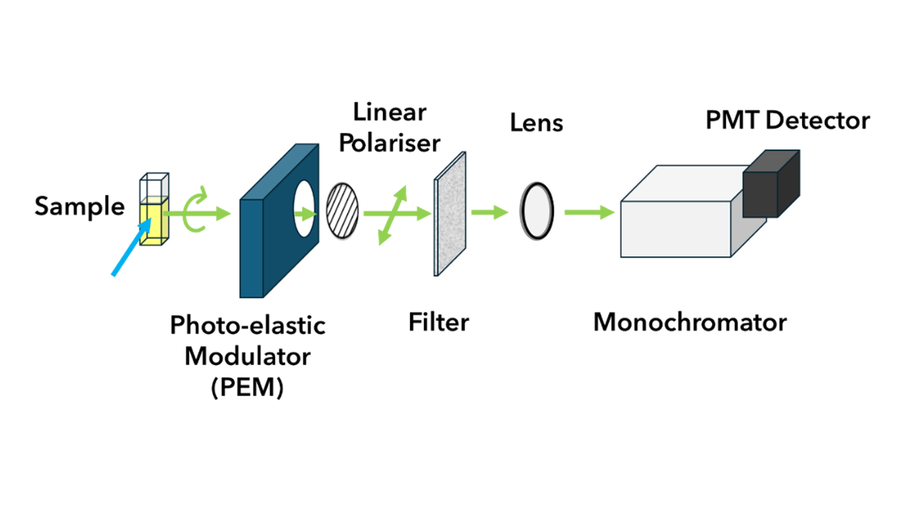 Figure 6. Schematic of experimental setup for CPL measurements.
The steps for measuring CPL are:
The primary measurement in CPL is the emission circular intensity differential (ECID).1 This quantity, defined by Equation 1, measures the difference in intensity between left- and right-circularly polarised emitted light.
Equation 1: Emission circular intensity differential (ECID)
![]()
IL and IR denote the intensities of left and right circularly polarised components of the emitted radiation, respectively. The circular polarisation of emitted fluorescence is also often expressed as a dissymmetry factor (glum) and is calculated using Equation 2:
Equation 2: Dissymmetry factor (glum)
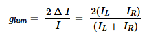
In this equation, glum is the luminescence dissymmetry factor. A glum value of ±2 corresponds to pure CPL emission, where + 2 refers to left-handed CPL, while -2 refers to right -handed CPL. A glum value of 0 corresponds to unpolarised luminescence.3
In general, the total luminescence observed in CPL is elliptically polarised rather than truly circularly polarised as described in Figure 3. This means that the small difference between the intensity of IL and IR must be measured, or the IL and IR components must be measured independently.
Circular Dichroism (CD) is a complementary chiroptical spectroscopy technique to CPL. While CD is an absorption spectroscopy method that relies on the differential absorption of left and right circularly polarised light (Figure 7), CPL spectroscopy provides information about the excited state of a sample.

Figure 7. The principles of Circular Dichroism (CD).
In CD, linearly polarised light is passed through a quarter-phase plate to achieve circularly polarised light. The circularly polarised light is used as incident light, and the absorption of this light by the sample is measured. The difference between absorption of left and right circularly polarised light probes the ground state optical properties of a sample.
Together, CD and CPL spectroscopy offer a comprehensive approach to studying chiral structures, making them complementary techniques.
While CPL spectroscopy is a specialised technique, its applications are diverse. This technique is a valuable tool for analysing the synthesis and properties of lanthanoid complexes, which are crucial components in LED technology. CPL spectroscopy can also be used for developing advanced materials for 3D displays and security markers. Finally, this technique can be applied to biological applications such as the study of proteins and the development of biosensors.
The ability of CPL to probe the properties of chiral structures makes it a powerful tool in various scientific and technological fields. A summary of some of the main applications of CPL spectroscopy are detailed in Table 1.
Table 1. Applications of CPL.
| Application | How is CPL used? |
| Chirality Detection | CPL spectroscopy can be used to detect and quantify chiral molecules, which are essential in many biological processes and pharmaceutical applications. |
| Biomedical Applications | CPL spectroscopy can be used to study biological macromolecule processes, such as protein folding transitions and DNA replication. |
| Biomolecular Sensing | By designing CPL-active probes that interact with specific biomolecules, researchers can develop sensitive and selective biosensors. |
| Security Applications | CPL materials are used to create security inks, tags and other anti-counterfeit measures. |
| Optical Devices | CPL-active organic materials can be used to create organic light-emitting diodes (OLEDs) which are used to create flexible, high contrast 3D displays. |
| Lanthanide Complexes | Chiral lanthanide complexes attract attention because of their efficient CPL and use in LED devices. |
| Environmental Sciences | CPL spectroscopy is used to detect and quantify chiral pollutants in the environment, such as pesticides and pharmaceuticals. |
Overall, CPL is a useful spectroscopic technique that can reveal the molecular and optical properties of chiral samples. By measuring the difference in intensity of left and right circularly polarised light emitted by a chiral sample, CPL provides valuable insights into the excited-state properties and chiral asymmetry.