The photomultiplier tube (PMT) is the detector of choice for high performance fluorescence spectrometers such as the Edinburgh Instruments FLS1000 and FS5, due to its excellent light sensitivity and ability to be used for both steady-state and time-resolved measurements. The PMT is a vacuum tube containing a photocathode, a series of electron multipliers called dynodes, and an anode; with a high voltage applied across them to drive electrons from the cathode towards the anode (Figure 1).
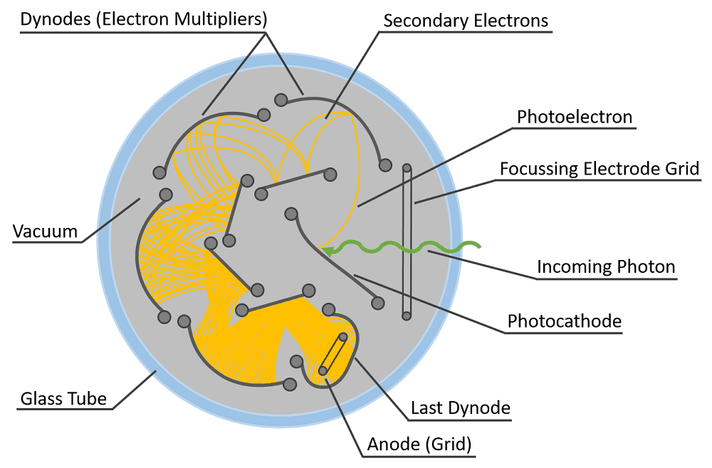 Figure 1. Top-down view of a side window PMT with nine dynodes in a circular-cage arrangement.1
When a photon strikes the photocathode, a photoelectron is emitted into the vacuum and accelerated by the applied voltage onto the first dynode where it is multiplied by secondary electron emission. This process of electron multiplication is repeated at each successive dynode in the chain, and the multiplied secondary electrons are then collected by the anode. Electron multiplication gains in excess of 1×10⁷ are readily achievable, meaning that a single photon generates a large pulse of current that can be easily detected; enabling highly sensitive fluorescence detection.
The downside of the high electron multiplication gain is that the PMT must operate under low light exposure; otherwise, the resulting excessive current can saturate and potentially damage the PMT detector. In certain measurements, particularly those with two emission processes occurring on drastically different timescales, such as fluorescence and phosphorescence, the risk of overexposing the PMT can be particularly problematic. To address this issue, the PMT can be time-gated to prevent overexposure by using an electronic shutter that switches the detector voltage “on” and “off.” This technical note introduces the gated PMT circuit add-on for the FLS1000 and FS5, and highlights scenarios where its use is advantageous.
In time-resolved photoluminescence spectroscopy the sample is excited with a short pulse of light, typically either from a laser or a flashlamp, and the photoluminescence photon arrival times are recorded to obtain a photoluminescence decay. The method used to measure and record those arrival times depends on the magnitude of photoluminescence lifetime. For fluorescent samples, which have short lifetimes on the order of ps or ns, the method of choice is time-correlated single photon counting (TCSPC) due to its excellent time resolution. For phosphorescent samples with lifetimes on the µs to ms timescale, the technique of single photon counting multichannel scaling (MCS) is instead used, as it enables faster data acquisition at low repetition rates.
The PMT saturation conditions and time-gating technique described in this section apply to phosphorescence measurements using MCS. TCSPC is typically not limited by PMT saturation and has its own set of conditions which are outside the scope of this technical note.
Many real-world samples exhibit both fluorescence and phosphorescence emission which can make the measurement of phosphorescence decays challenging. As an example, consider a 1:1 mixture of two species with equal absorption coefficients at the laser excitation wavelength and equivalent photoluminescence quantum yields but one species has a lifetime of 100 ns and the other 100 µs.
Over the course of their complete photoluminescence decays both species will emit the same number of photons; however, the species with the shorter lifetime will emit those photons over a smaller interval of time. The ratio of the photon emission rate of the two species is given by the ratio of their lifetimes; the peak photons per second emitted by the 100 ns species is therefore 1000x higher than from the 100 µs species.
This effect is illustrated in Figure 2, which shows the photoluminescence decay from Tb3+ ions embedded in a fluorescent medium. The initial spike, which occurs essentially instantaneously on the millisecond timescale of Figure 2, arises from the fluorescence emission, while the long tail corresponds to phosphorescence from the Tb3+ ions. It can be observed from Figure 2, that the number of photons recorded during the fluorescence is ~100 times greater than during the phosphorescence emission, which in turn means that the number of photons per second impacting the detector is ~100 times greater during the fluorescence emission.
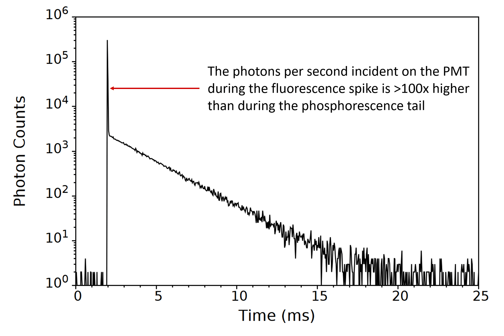
Figure 2: Photoluminescence decay from Tb3+ ions embedded in a fluorescent medium measured without PMT gating.
This disparity in the peak photon count rates between the fluorescence and phosphorescence components has important consequences when trying to measure phosphorescence decays. Above 2 million counts/s the PMT will begin to saturate and the photon counting becomes nonlinear. Increasing the count rate further to 10 – 100 million counts/s, the high current in the PMT may lead to voltage drops and reduced gain resulting in distorted phosphorescence decay profiles and potential damage to the PMT.
Photoluminescence samples are generally excited using high-power lasers or flashlamps to achieve a sufficient signal; however, under these conditions, the peak count rate during the fluorescence spike can easily exceed 100 million counts per second, which can damage the detector.
To avoid detector oversaturation, one option is to simply attenuate the number of photons reaching the PMT (either by reducing the excitation power or reducing the emission bandwidth) to reduce the peak count rate during the fluorescence spike to a safe level. However, this is an extremely inefficient way to measure the phosphorescence decay as the count rate is being limited by the short-lived fluorescence. This leads to a very low phosphorescence signal, with the counting rate falling below the minimum required threshold.
A superior solution to this problem is to time-gate the PMT so that it is protected from overexposure during the fluorescence emission (Figure 3).
The time-gating is achieved by adding a gating-circuit to the PMT socket that switches off the voltage to the first three dynodes (electron multipliers) of the chain; greatly reducing the electron multiplication gain of the PMT. The gate delay (the time between the laser or flashlamp pulse and the start of the gate) and the width of the gate can be set in the Fluoracle software to only detect within the time region of interest and exclude the high-intensity fluorescence. The gating circuit is available as an add-on for the PMT-900 and PMT-980 which are the two visible detector options of the FLS1000 and FS5.
The number of dynodes to switch off is a trade-off between effective fluorescence suppression and the time-response of the gating circuit. The switching of three dynodes provides a good balance between high fluorescence suppression (>1×10⁶ suppression ratio) and a short rise time of <15 µs which is suitable for the majority of phosphorescence emitters. If your application requires a shorter rise time, please send your required specifications to our sales team.
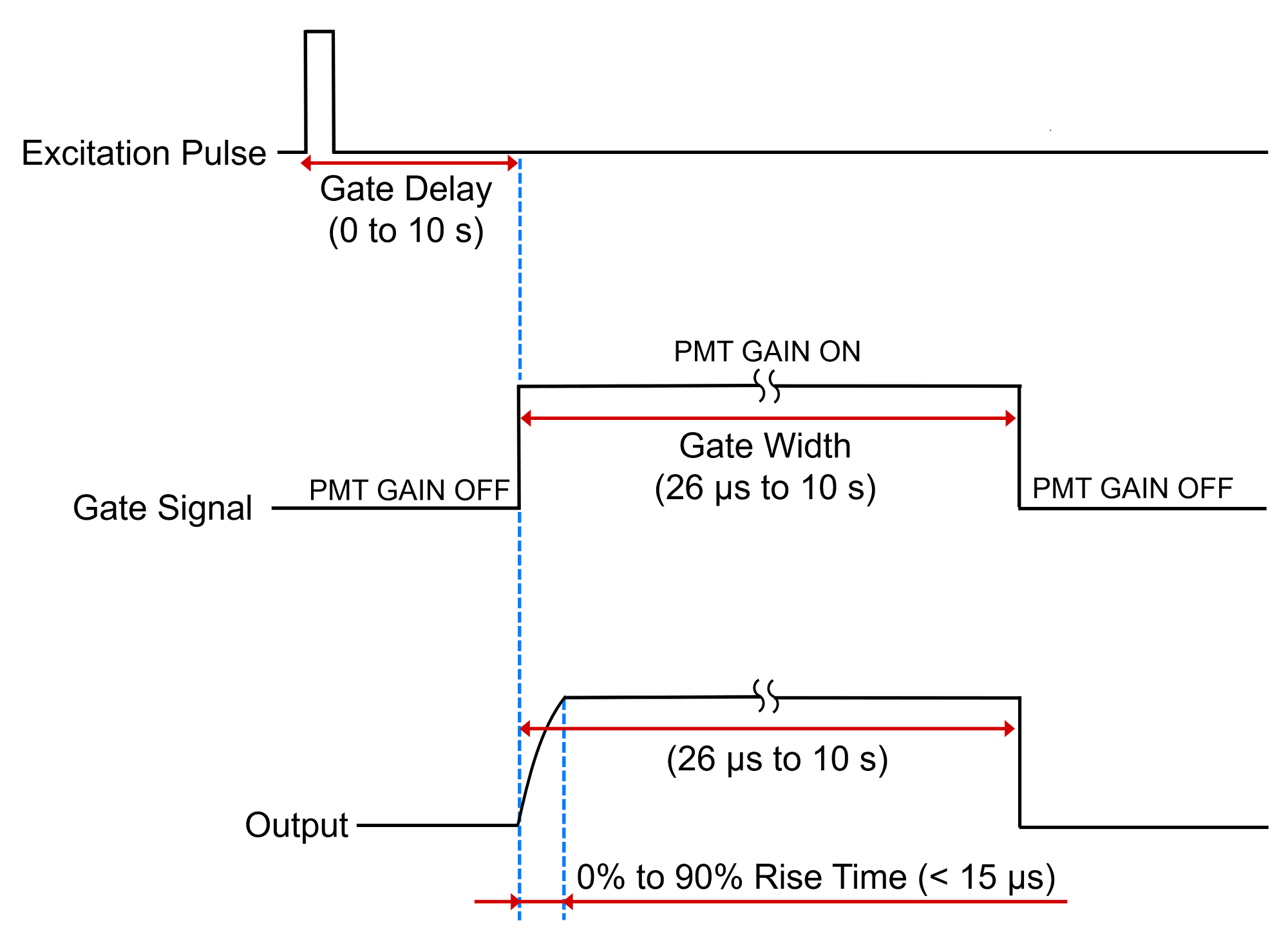 Figure 3: Principle of PMT Gating in the FLS1000 and FS5.
The photoluminescence decay of the Tb3+ sample was remeasured with PMT gating enabled and is shown in Figure 4. The gate delay was set to 0.5 ms and the gate width to 20 ms; it can be seen that the phosphorescence decay of the Tb3+ is recorded while avoiding the fluorescence. By using PMT gating the time to acquire the phosphorescence decay is decreased, as higher phosphorescence count rates can be used without the risk of overexposing the detector with fluorescence.
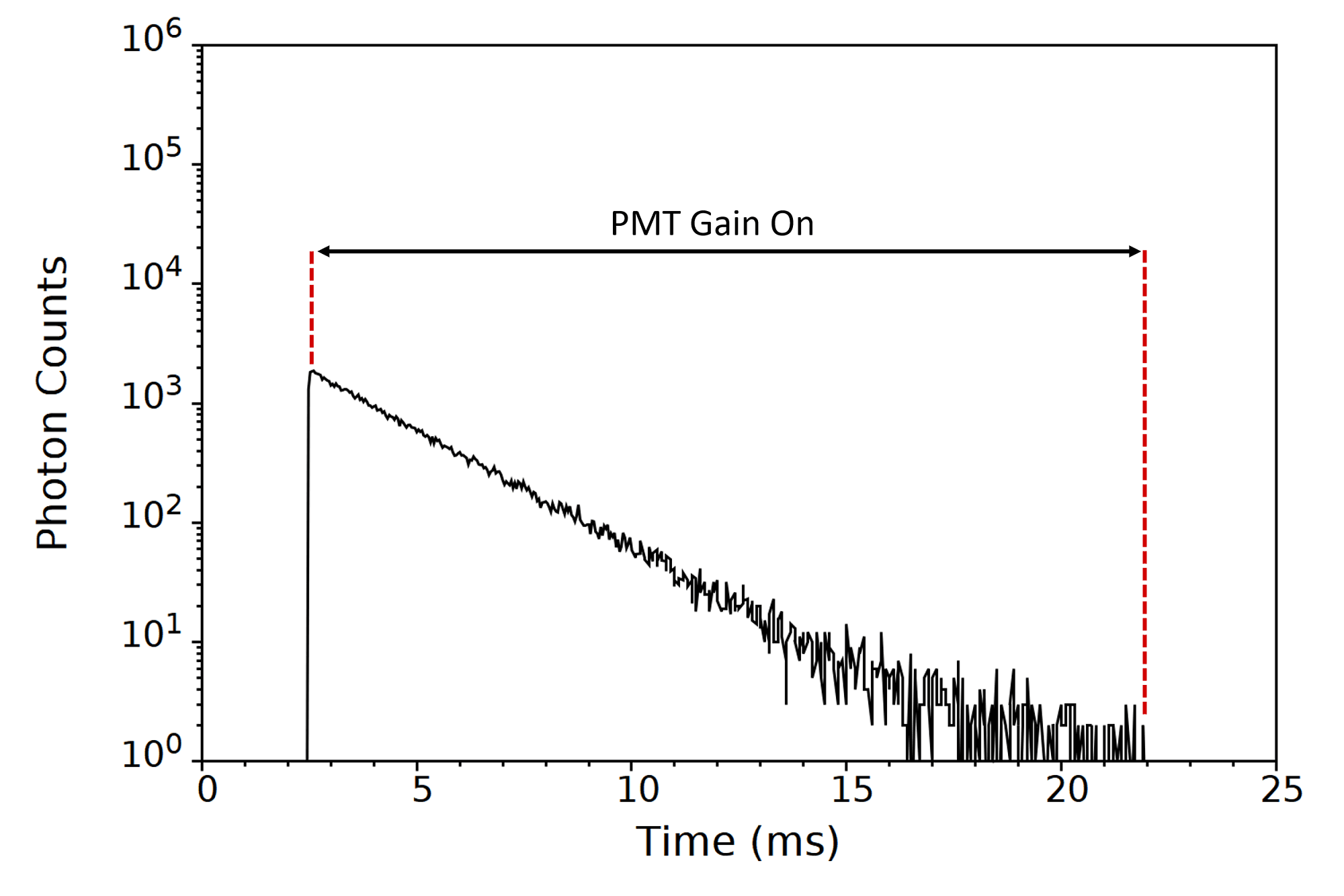
Figure 4: Photoluminescence decay from Tb3+ ions embedded in a fluorescent medium measured with PMT gating enabled.
PMT gating is also a powerful and easy to use method of separating overlapping fluorescence and phosphorescence contributions in spectra. In gated spectral measurements the sample is excited with a pulsed light source and the number of photons within the specified gate are recorded as a function of emission wavelength. Figure5 shows the spectrum of the same Tb3+ sample discussed above. When the spectrum is measured without PMT gating there is a broad fluorescence background which distorts the spectrum. By enabling detector gating and only recording the photons within the 20 ms gate illustrated in Figure 4, the fluorescence component is excluded and the true phosphorescence spectrum obtained.
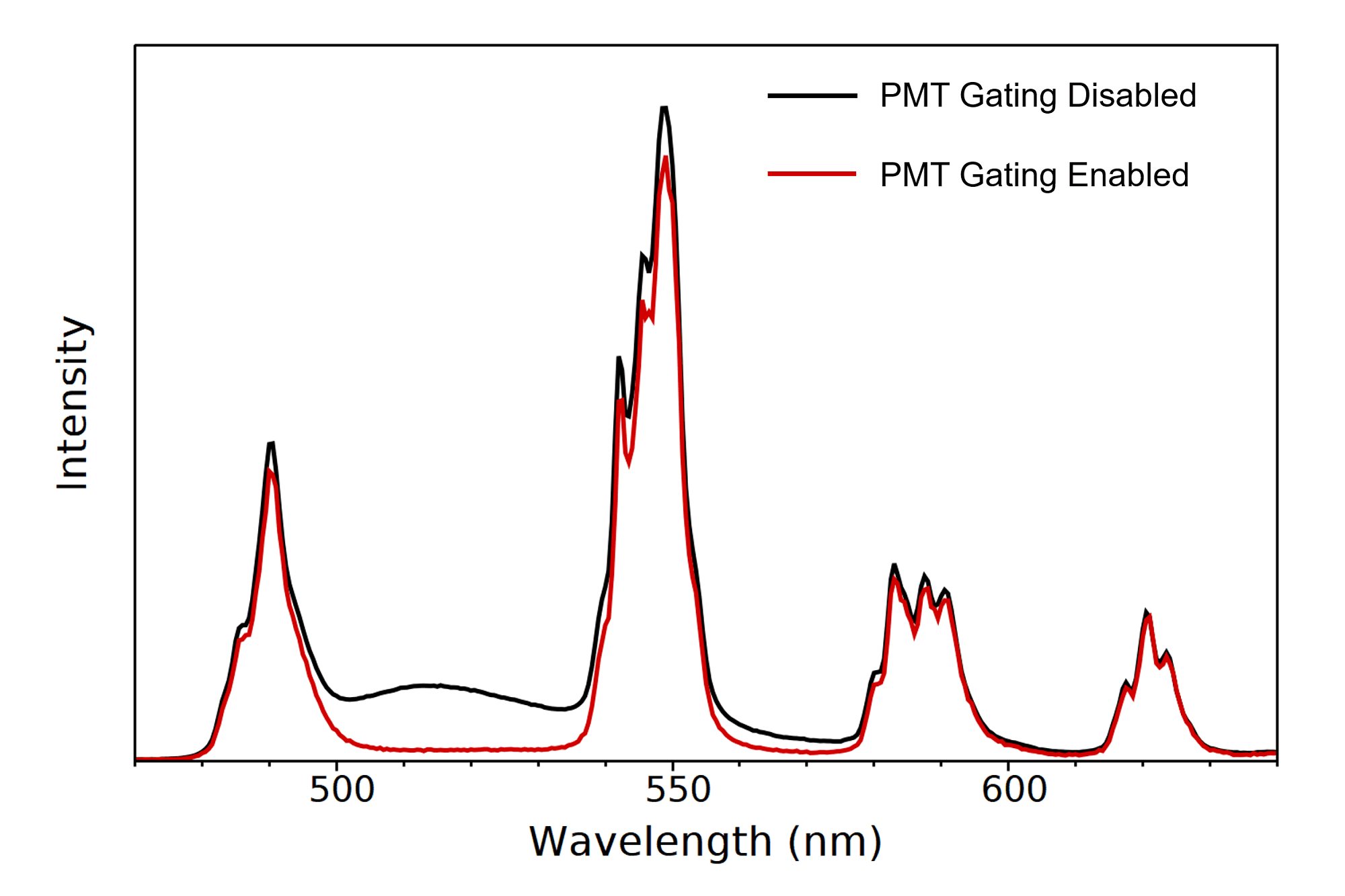
Figure 5: Removal of the fluorescent background from Tb3+ emission using PMT gating.
Fluorescence and phosphorescence can both originate from the same species, as observed in certain organic molecules. An example is the investigation of new emitters for OLEDs, where accurate fluorescence and phosphorescence spectra are required to calculate energy level splittings. When the molecule is cooled to 80 K, non-radiative decay processes and molecular motion are suppressed, leading to an enhanced phosphorescence signal and an emission spectrum that exhibits overlapping contributions from both fluorescence and phosphorescence. PMT gating can be used to separate the fluorescence and phosphorescence and record their spectra (Figure 6).
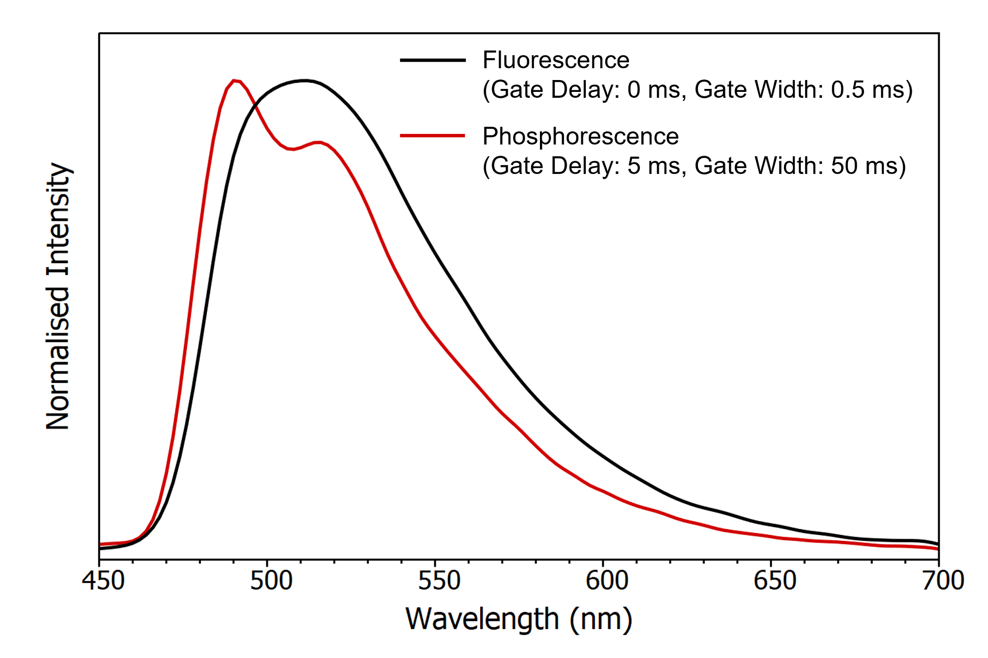
Figure 6: Fluorescence and phosphorescence spectra of an OLED emitter measured at 80 K using detector gating to isolate the two spectra.
Here, the sample was excited with a 500 µs laser pulse (VPL-375 pulsed diode laser) and two spectra recorded with different gate parameters. One gate coincided with the laser pulse to obtain the fluorescence spectrum and the other delayed 5 ms after the laser pulse to measure the phosphorescence.
The gated photomultiplier tube circuit add-on is an excellent option for the measurement of samples which contain emission occurring on different timescales. By time-gating the PMT-900 or PMT-980 detectors, the fluorescence emission can be removed, allowing phosphorescence decays to be acquired more rapidly and efficiently, without risking damage to the detector. In addition, the gating can be used to remove unwanted background fluorescence from spectra and isolate overlapping fluorescence and phosphorescence contributions to obtain distinct spectra.
1. Photomultiplier Tubes: Basics and Applications 3rd Ed. Hamamatsu Photonics