Thermally Activated Delayed Fluorescence (TADF) is a mechanism for enhancing the efficiency of Organic Light Emitting Diodes (OLEDs) by harvesting triplet excitons. TADF has therefore attracted widespread interest in the OLED community and research into TADF and OLEDS is a popular application of our FS5 and FL1000 photoluminescence spectrometers. In this article, the operating principal and promise offered by TADF OLEDs is introduced.
OLEDs are a type of light emitting diode where the emissive electroluminescent layer is composed of carbon based (organic) semiconductors, typically aromatic small molecules, in contrast to the inorganic crystalline semiconductors used in traditional LEDs. OLED displays are now routinely found in smartphones and high-end televisions due to their lower power consumption, high brightness, lightweight and higher contrast, compared to traditional LCD displays.1

Figure 1: iPhone X with OLED display.
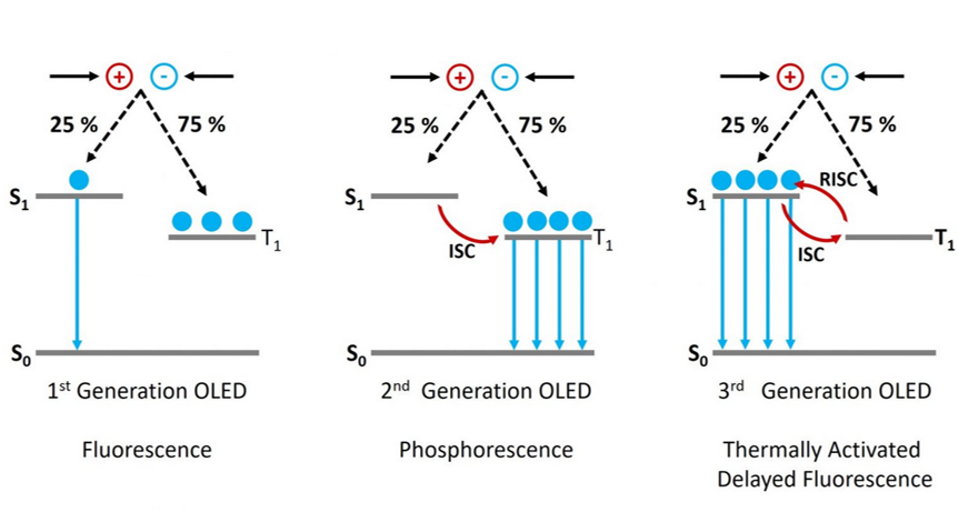
In an OLED a voltage is applied across an organic semiconductor layer resulting in the injection of electrons and holes. These electrons and holes travel through the semiconductor, before encountering each other and forming a strongly bound electron hole pair called an exciton (see Figure 2). Electrons and holes are fermions with half integer spin, and depending on the relative orientations of the two spins, the exciton can either have a total spin of zero (S = 0) which is called a singlet exciton or a total spin of one (S = 1) which is a triplet exciton. As shown in Figure 2, there are three combinations of half integer spins that form an S = 1 exciton and only one combination which forms an S = 0 (hence the names triplet and singlet!). This means that 75 % of the excitons formed in an OLED will be in the triplet state and only 25 % in the singlet. This is a major issue in the creation of an efficient OLED, as radiative decay from the triplet state (T1) to the ground state singlet (S0) is forbidden due to conservation of angular momentum. 75 % of the electrons and holes injected into the device are therefore wasted and the maximum internal quantum efficiency of the OLED is limited to 25 % (Figure 3, 1st Generation).

Figure 2: The triplet problem in OLEDs. Due to spin statistics 75% of the excitons formed inside the OLED will be in the triplet state.
The first solution to this problem was to move away from the pure organic compounds used in 1st generation OLEDs towards organic compounds that incorporate heavy metals such as iridium. The use of heavy metals increases the spin orbit coupling (SOC) between the exciton spin angular momentum and the orbital angular momentum. The SOC results in the radiative transition from the T1 to the S0 being no longer strictly forbidden and the T1 state therefore becomes emissive (Figure 3, 2nd Generation). In addition the SOC promotes intersystem crossing (ISC) between the S1 and the T1 which further populates the T1 state at the expense of the S1. OLEDs using this mechanism are known as 2nd generation or PhOLEDs and have internal quantum efficiencies approaching 100 %.

Figure 3: The operating principle of 1, 2 and 3 generation of OLEDs.
Each pixel of an OLED display is actually made up of three separate OLEDs, a red, a green and a blue. The green and red emitters used in commercial OLED displays are 2nd generation phosphorescent materials, and are therefore efficient. However, making a stable deep blue phosphorescent emitter has proved challenging and to date no suitable 2nd generation blue emitter has been found. Commercial displays are therefore forced to use inefficient 1st generation fluorescent blue emitters and as a result, the blue OLED consumes much more power than the red and green. For portable electronics, where battery life is crucial, this is a major problem and there is great demand for an efficient blue emitter.
A promising solution to this problem is to move away from phosphorescent emitters and towards fluorescent emitters that exhibit a phenomena known as Thermally Activated Delayed Fluorescence (TADF). The concept of TADF is not new as it was first reported by Perrin et al. back in 1929,2 and was investigated by a few others throughout the 20th century.3-4 However it was in 2012 when Chihaya Adachi used the TADF mechanism to create an efficient OLED without using phosphorescence,5 that TADF received widespread attention and is now being investigated by many research groups across the world.
A simplified description of the TADF mechanism is as follows. In a TADF emitter the S1 and T1 levels are strongly coupled which allows ISC between the two levels. In addition the molecule is designed so that the energy difference between the S1 and T1 (ΔEST) is much smaller than in typical organic molecules, with a ballpark ΔEST for efficient TADF being less than 100 meV.5 This small energy gap enables reverse intersystem crossing (RISC) to occur, where excitons in the T1 are converted to S1 in a thermally activated process (Figure 3, 3rd Generation). Once in the S1 state the excitons can decay back to the S0 ground state via fluorescence. Since RISC is a slow process, the fluorescence from the once triplet excitons occurs later than the fluorescence from the excitons created directly in the S1 state and is therefore called delayed fluorescence, hence the name TADF. It should be noted that this is a highly simplified description of the TADF mechanism and for a more complete description of the many nuances of TADF I recommend the overview of TADF theory by Penfold et al.6
Using the TADF mechanism, internal quantum efficiencies of 100 % can be achieved and it is hoped that TADF will allow the creation of a stable and high efficiency blue emitter. Many companies are therefore actively researching TADF, in an effort to be the first to bring a blue TADF emitter to market. One of the companies at the forefront of this effort is cynora GmbH, who aim to have a blue TADF emitter in commercial products by 2020. Cynora are customers of Edinburgh Instruments, using a FS5 Spectrofluorometer to aid in the development of these new materials. It will be interesting to follow the progress of this burgeoning field as it moves forward and whether it can achieve the dream of a stable high efficiency blue emitter.
1. Y. Wong & E. Zysman‐Colman, Adv Mater. 29 1605444 (2017)
2. R. Delorme & F. Perrin, J. Phys. Rad. Ser. 10, 177 (1929)
3. N. Lewis, D. Lipkin & T. T. Magel, J. Am. Chem. Soc., 63, 3005 (1941)
4. C. A. Parker and C. Hatchard, Trans. Faraday Soc. 57 1894 (1961)
5. H. Uoyama, K. Goushi, K. Shizu, H. Nomura & C. Adachi, Nature 492, 234 (2012)
6. J. Penfold, F. B. Dias & A. P. Monkman, Chem. Commun. 54 3926 (2018)