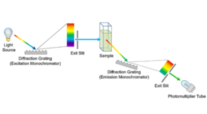
Diffraction gratings are essential components that separate light into its constituent wavelengths. Diffraction gratings can be both transmissive and reflective. This Spectral School focuses on reflective diffraction gratings (Figure 1) which are used in Czerny-Turner monochromators regularly found in optical spectrometers. Reflective diffraction gratings are typically further categorised by their manufacturing method.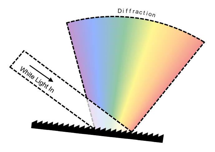
Figure 1: Diffraction of Light by a Reflective Grating. White light being split into its constituent wavelengths by the process of diffraction.
Ruled gratings – sometimes referred to as blazed gratings – are manufactured by physically scratching or etching material away from a substrate, following a precise template called the master. This produces sawtooth-shaped grooves in a process analogous to cutting a key, where the pattern of grooves on the master is copied to the substrate to produce the new grating. Based upon the specific groove angle, density and substrate material, the wavelength of maximum throughput efficiency – the blaze wavelength – can be finely tuned.
This manufacturing method, however, is susceptible to periodic imperfections. If a periodic imperfection is present, for example a repeating error in the spacing or shape of the grooves, light incident upon the grating can be reflected at abnormal angles. This increases stray light artefacts and can lead to spectral ghosts.
Optical detectors, while capable of measuring the intensity of light, cannot inherently distinguish the wavelength of individual photons. Put simply, they only register the arrival of photons. Consequently, if photons of two different wavelengths can be reflected from the grating at the same angle, photons of both wavelengths arriving at the detector will be counted as the wavelength expected from the bulk grating. An example of this is shown in the diagram below (Figure 2).
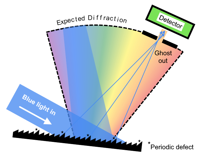
Figure 2: Cause of Spectral Ghosts. A periodic defect on the ruled diffraction grating causing some blue photons (represented by the arrows) to be reflected at the same angle as expected of orange photons of the bulk grating. Since the detector cannot determine wavelength – these blue photons would be counted as orange in the recorded spectrum.
In Figure 2, blue light is incident upon a ruled grating. Based upon the relative angle of the grating and incident light, only orange light would be expected to pass though the slit towards the detector. Since there is only blue light diffracted by the grating, one would expect no photons to reach the detector. The grating, however, has a periodic defect. This causes a small proportion of the incident blue light to be diffracted at the angle expected from orange light. These blue photons arriving at the detector would then be counted as orange by the instrument. This misidentification manifests as a spectral ghost; false signal from photons appearing at an incorrect wavelength in the measured spectrum.
Spectral ghosts can be distinguished from other stray light effects. One approach is to change the excitation wavelength of the light source. If the suspect peak is a spectral ghost originating from scattered excitation light, the peak position will shift with the change in excitation wavelength. Another method for identifying spectral ghosts involves using optical filters. If a filter blocks the wavelength responsible for the spectral ghost, the suspect peak disappears. This confirms that the detected photons were not the wavelength recorded, thus revealing the presence of a ghost. Both of these effects are shown in the spectra below (Figure 3).
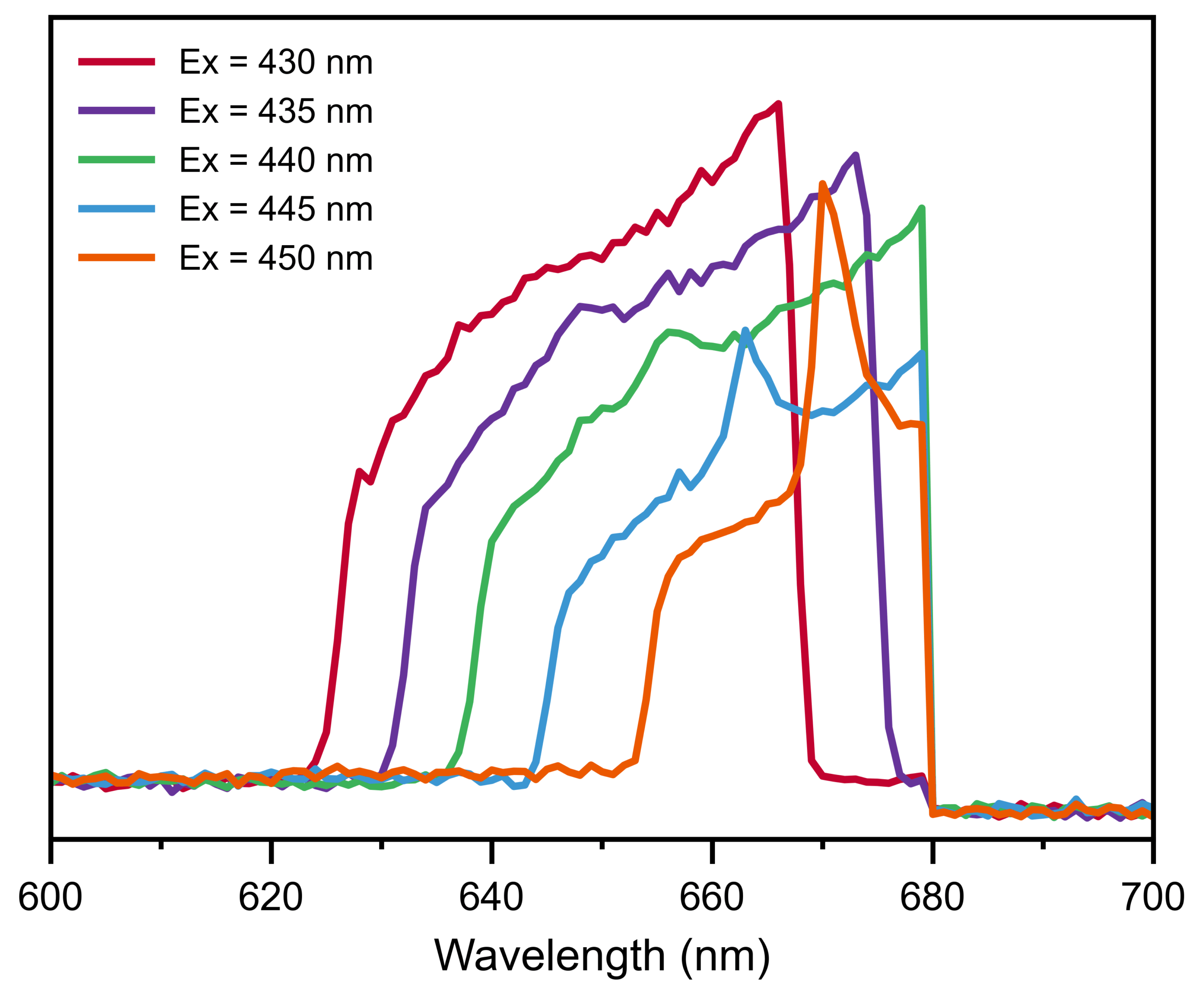
Figure 3: Identifying spectral ghosts. Excitation emission map of scattered light from a PTFE block excited at 430 nm – 450 nm. The peak measured at around 660 nm moves as excitation wavelength is changed – suggesting a spectral ghost. This is confirmed when the ghost peak is truncated by the order sorting longpass filter introduced at 680 nm.
These spectra are from an excitation/emission map of a scattering block of PTFE – excited from 430 nm to 450 nm. PTFE is highly reflective and has no photoluminescence emission within this excitation range; however, a peak at around 660 nm is observed. Changing the excitation wavelength changed the position of the observed peak, suggesting a spectral ghost. This was confirmed by the ghost peak being truncated when excitation wavelength was increased beyond 440 nm. Truncation occurs because the instrument this data was acquired on has an order sorting longpass filter introduced to the emission pathway at 680 nm. Typically this filter is used to prevent second-order effects; however, here it absorbs the scattered excitation photons which were responsible for the spectral ghost.
Holographic gratings are manufactured using a different approach. Holographic gratings are fabricated using laser interference techniques from two coherent laser beams: a reference beam and an object beam. The object beam illuminates a master grating, and the resulting diffracted light interferes with the reference beam on a photosensitive substrate. This interference pattern, a series of bright fringes (constructive interference) and dark fringes (destructive interference), corresponds to the groove structure of the desired grating. The exposed substrate is then developed, permanently recording the interference pattern onto the new grating, resulting in sinusoidal-shaped grooves.
The precision with which this interference pattern can be controlled allows for the creation of gratings with higher accuracy and fewer imperfections than ruled gratings. Critically, the holographic manufacturing process – relying on the interference of light waves as opposed to mechanical scribing – inherently avoids the periodic defects that cause spectral ghosts in ruled gratings. This produces gratings with improved stray light reduction as compared to ruled gratings.
It may seem like holographic gratings are always preferred; however, there are more factors to consider than stray-light performance. A brief summary of these are shown in Table 1 below.
Table 1: Summary of the optical properties of ruled gratings versus holographic gratings.
| Ruled Grating/Blazed Grating | Holographic Grating | |
|---|---|---|
| Groove Shape |  | 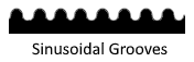 |
| Ghost/Stray Light | Worse | Better |
| Quantum Efficiency | Better | Worse |
| Spectral Dispersion | Identical. Dictated by groove density. | Identical. Dictated by groove density |
While it is true that holographic gratings offer improved stray light performance, ruled gratings also have their benefits. Specifically, ruled gratings tend to have higher efficiency. This is because their sawtooth groove shape allows for greater control of the proportion of light of a chosen wavelength being diffracted into the desired order.
Holographic gratings on the other hand have improved stray light performance – owing to reduced manufacturing defects. Most other properties such as spectral dispersion, and spectral resolution are dictated by groove density and are therefore identical between the two grating types.
In summary, ruled gratings can have repeating, periodic defects due to their manufacturing process. These defects can cause two wavelengths of light to be diffracted from the grating at the same angle. Since optical detectors cannot distinguish between photons of different wavelengths, all photons arriving at the detector are counted as the same wavelength. This results in a stray light artifact called a spectral ghost.
Spectral ghosts can be avoided using holographic gratings which are manufactured by a different process. This process does not produce the periodic defects found in ruled gratings and therefore holographic gratings have improved stray light performance.