In this Spectral School tutorial we discuss the phenomena of second order diffraction through a monochromator and the problems it can cause in fluorescence spectroscopy.
In fluorescence spectroscopy, monochromators are used to select the excitation and emission wavelengths. A typical fluorescence spectrometer will consist of two monochromators; an excitation monochromator to select the desired excitation wavelength and an emission monochromator to select which wavelength reaches the detector. Monochromators utilise diffraction gratings in order to isolate the desired wavelength from incident broadband light. The broadband light is shone on the diffraction grating and the different wavelengths that comprise the light are diffracted at different angles in order to satisfy the grating equation,

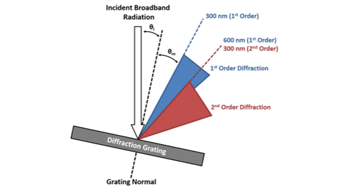
where m is the order of the diffraction, λ is the wavelength of the diffracted light, d is the groove spacing of the grating, θm is the angle between the incident light and the grating normal, θί is the angle between the diffracted light and the grating normal. It can be seen that for constant θi each wavelength of light will be diffracted at a different angle θm which allows the monochromator to isolate the desired wavelength. It can also be seen that for constant θm and constant λ the equation is satisfied with different angles θm depending on the diffraction order m which can take positive and negative integer values (…-2, -1, 0, 1, 2…). A value of ±1 is termed first order diffraction and occurs closet to the grating normal and is the highest in intensity. Similarly a value ±2 is known as second order diffraction and occurs at a shallower angle and is weaker in intensity. Diffraction at higher orders follows a similar pattern of increasing angle away from the normal and reducing intensity.
In a monochromator it is only the first order diffraction (either +1 or -1) that is used to select the desired wavelength and the higher orders are unwanted. However, due to the broad range of wavelengths being diffracted, the angle ranges occupied by the first and second order diffraction are not unique. This is illustrated in Figure 1 where the blue cone represents the range of angles where the light is first order diffracted and the red cone is the range of angles where the light has been diffracted second order and there is an overlap region shared between these ranges. This shared range can also be seen from the grating equation. Consider light at 600 nm that is first order diffracted (m = 1, λ = 600 nm) and light at 300 nm that is second order diffracted (m = 2, λ = 300); it is clear that the left hand side of the grating equation is the same for both cases and the angle of the diffracted light must therefore be equivalent. The consequence of this is that when the monochromator is set to transmit 600 nm, a small fraction of 300 nm light will also be transmitted which can be problematic for fluorescence spectroscopy.
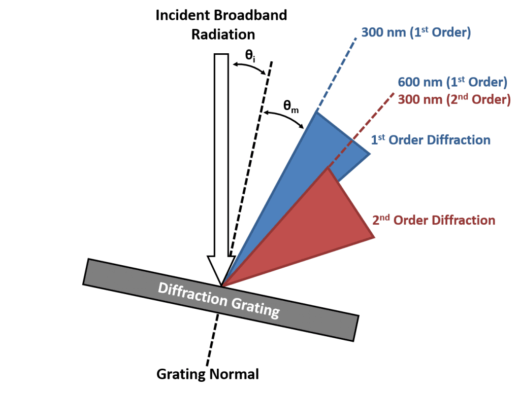
Figure 1: The overlapping orders of a diffraction grating. Adapted from Lakowicz.²
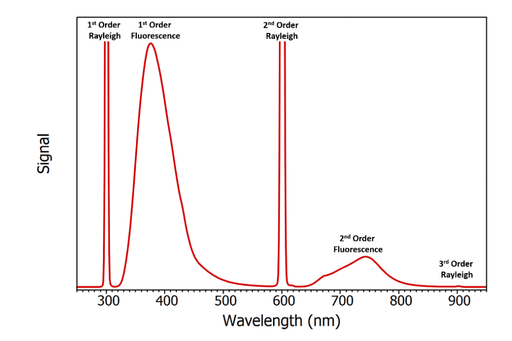
Figure 2: Example of second order artefacts in a broad fluorescence emission spectrum of a solution of 2-aminopyridine mixed with Ludox excited at 300 nm. The spectrum was recorded using the FLS1000 Photoluminescence Spectrometer with the order sorting filter wheel on the emission monochromator disabled. The spectrum has not been corrected for grating and detector efficiency wavelength responses.
Second order diffraction is a particular problem for scattering samples such as powders, crystals, and colloidal suspensions. To show the effect that second order diffraction has on fluorescence spectra, a scattering fluorescent sample was prepared by mixing a solution of the fluorescent dye 2‑aminopyridine with Ludox which is a colloidal suspension of silica nanoparticles and serves as a scatterer. The solution was excited at 300 nm and the emission spectrum measured over a range of 250 nm to 950 nm as shown in Figure 2 using the FLS1000 Photoluminescence Spectrometer with the order sorting filter (see following section) of the emission monochromator disabled. The first peak at 300 nm corresponds to the Rayleigh scatter of the 300 nm excitation light that has been first order diffracted in the emission monochromator. This is followed by the first order fluorescence of the 1-aminopyridine which peaks at 380 nm. These peaks are then repeated as second order artefacts with a Rayleigh scatter peak at 600 nm and a fluorescence peak at 760 nm. A weak third order Rayleigh scatter peak can also just be seen at 900 nm. Mistaking second order artefacts as true fluorescence emission is a common mistake amongst inexperienced fluorescence users and has even been the cause of erroneous reports in the literature. One example of this is the publication of a paper which reported new weak long wavelength emission bands of tryptophan and tyrosine at 675 nm and 600 nm that were in addition to the well-known UV emission of these protein residues.3 Six months later Hutnik et al. published a rebuttal which showed that the supposed long wave fluorescence was simply the second order diffraction of the true tryptophan and tyrosine UV emission at 340 nm and 300 nm.4
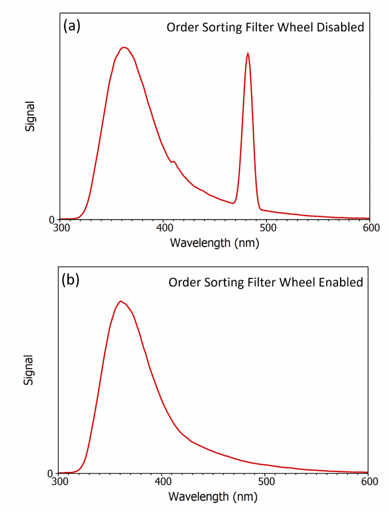
Figure 3: Distortion of the fluorescence spectrum of 2-aminopyridine due to second order scatter when excited at 240 nm and the benefit of order sorting filters. (a) Spectrum measured with the order sorting filter wheel disabled and (b) measured with the order sorting filter wheel enabled. The spectra were measured using the FLS1000 Photoluminescence Spectrometer and have been corrected to account for the grating and detector efficiency wavelength responses.
Mistaking and publishing a second order artefact is an extreme example but a more common problem is that the second order scatter often overlaps with the fluorescence emission that is being measured and distorts the spectrum. Figure 3a shows the emission spectrum of the same Ludox / 2‑aminopyridide sample that was used in Figure 2 but the excitation wavelength has been shifted to 240 nm and the emission range narrowed. The second order scatter is now at 480 nm and overlaps with the tail of the fluorescence of 2-aminopyridine which prevents accurate measurement of the spectrum. The solution to this problem is to use order sorting filters inside the monochromator. Order sorting filters are long pass filters which only transmit wavelengths above the cut-off wavelength of the filter. The principle of order sorting filters inside the monochromator is illustrated in Figure 4, where the order sorting filters are mounted in a filter wheel located in front of the exit slit. When the monochromator is set to transmit 300 nm the diffraction grating is rotated so that the 300 nm diffracted light is directed at the exit slit of the monochromator and the filter wheel is rotated so that there is no long pass filter in the light path and 300 nm light is output from the monochromator as desired (left image). When the monochromator is set to transmit 600 nm light the diffraction grating is rotated so that first order diffracted 600 nm light is directed at the exit slit which is accompanied with a small amount of second order 300 nm light. The filter wheel is rotated so that there is a 400 nm long pass filter in front of the exit slit which transmits the desired 600 nm light while blocking the unwanted 300 nm light (right image).

Figure 4: The principle of using order sorting filters for second order diffraction removal in a monochromator.
The benefit of ordering sorting filters is shown in Figure 3b where the spectrum was remeasured with the automated order sorting filer wheel of the emission monochromator of FLS1000 now enabled. The order sorting filter removes the second order scatter peak at 480 nm and true spectrum of 2‑aminopyridine is obtained. The Edinburgh Instruments FLS1000 and FS5 spectrometers are equipped with order sorting filter wheels on both the excitation and emission monochromators as standard. These filter wheels are enabled by default and are fully automated, with the Fluoracle® software of the FLS1000 and FS5 selecting the appropriate filters to use based on the choice of excitation wavelength and emission wavelengths. These automatic filter wheels allow the user to measure broad fluorescence spectra without ever worrying about second order artefacts distorting their measurements.
1. Introduction to Fluorescence, D. M. Jameson, CRC Press (2014)
2. Principles of Fluorescence Spectroscopy 3rd, J. R. Lakowicz, Springer (2006)
If you have enjoyed our blog post on second order diffraction and would like be one of the first to see all the latest news, applications, and product information then sign-up to our infrequent newsletter via the red sign-up button below, and follow us on social media.